Ink reservoir, ink jet head structure including ink reservoir, and ink jet recording apparatus including ink reservoir

a technology of ink jet and recording apparatus, which is applied in the field of ink jet recording apparatus including ink reservoir, which can solve the problems of disadvantageous weight of the apparatus, affecting the scanning speed of the cartridge, and affecting the quality of the data, so as to reduce the amount of ink remaining, and reduce the amount of ink absorbing member

Inactive Publication Date: 2005-11-22
CANON KK
View PDF6 Cites 20 Cited by
  • Summary
  • Abstract
  • Description
  • Claims
  • Application Information

AI Technical Summary

Benefits of technology

[0033]As described above, the ink reservoir, the ink jet head structure, and the ink jet recording head according to the present invention are each constituted so that the area in the sub-tank which stores the ink includes the absorbing member arrangement area in which the ink absorbing member is arranged and the absorbing member non-arrangement area in which the ink absorbing member is not arranged. That is, the ratio of the ink absorbing member in the area which stores the ink according to the present invention is lower than that of the ink absorbing member which entirely occupies the area which stores the ink. Therefore, it is possible to reduce the amount of the ink remaining in the ink absorbing member without being used by as much as the reduced amount of the ink absorbing member. It is also possible to reduce the air accumulation in the ink absorbing member which is generated during ink refilling by reducing the amount of the ink absorbing member. Therefore, the ink filling amount in the sub-tank can be increased. Thus, the ink jet recording head according to the present invention can increase the usable ink amount.
[0034]Furthermore, the ink reservoir, the ink jet head structure, and the ink jet recording head according to the present invention are each constituted so that the area in the sub-tank which stores the ink right after the ink is supplied includes an absorbing member arrangement area in which the ink absorbing member is arranged and an absorbing member non-arrangement area that is a space in which the ink absorbing member is not arranged and which temporarily stores the ink, and so that if the ink discharge amount that is the specified amount by which the ink is discharged is V1, the volume of the absorbing member non-arrangement area is V2, and the volume of the area in the sub-tank which stores the ink right after the ink is supplied is V3, then the volumes V1, V2, and V3 are set to satisfy V3≦20V1 and 0.7V1≦V2≦V1. By providing the absorbing member non-arrangement space having the ink amount equal to that by which the ink is discharged in the ink discharge operation right after the supply of the ink, the ink which is not impregnated into and held by the ink absorbing member or so-called raw ink is promptly discharged in the ink discharge operation right after ink filling. Therefore, it is possible to maintain an appropriate negative pressure against the ink discharge port at need and prevent poor discharge during recording and the leakage of the ink from the ink discharge port while recording is not performed.

Problems solved by technology

Since the head cartridge 201b which holds the ink therein is provided on the carriage 201a, the weight of the apparatus is disadvantageously heavy and the heavy weight hampers high rate scanning of the cartridge 201a.
201b is made small in size so as to reduce the weight of the apparatus, the number of sheets on which data can be recorded disadvantageously decreases.
A mechanism of the apparatus is disadvantageously complicated since the ink cartridge 301c provided on the main body side is connected to the ink jet recording head 301 by the ink supply tube 301d, with the result that it is disadvantageously difficult to make the apparatus small in size.
However, this mechanism is often quite complicated, delicate and expensive.
Therefore, it is unnecessary to conduct air discharge control.
Due to this, it is difficult to reduce the total ink amount.
As a result, the ink utilization efficiency is disadvantageously deteriorated (see FIG. 15A).
The mechanism disadvantageously pushes up cost depending on a structure thereof and the sub-tank is disadvantageously made large in size.

Method used


Image

  • Ink reservoir, ink jet head structure including ink reservoir, and ink jet recording apparatus including ink reservoir
  • Ink reservoir, ink jet head structure including ink reservoir, and ink jet recording apparatus including ink reservoir
  • Ink reservoir, ink jet head structure including ink reservoir, and ink jet recording apparatus including ink reservoir

Examples


embodiment 1

(Embodiment 1)

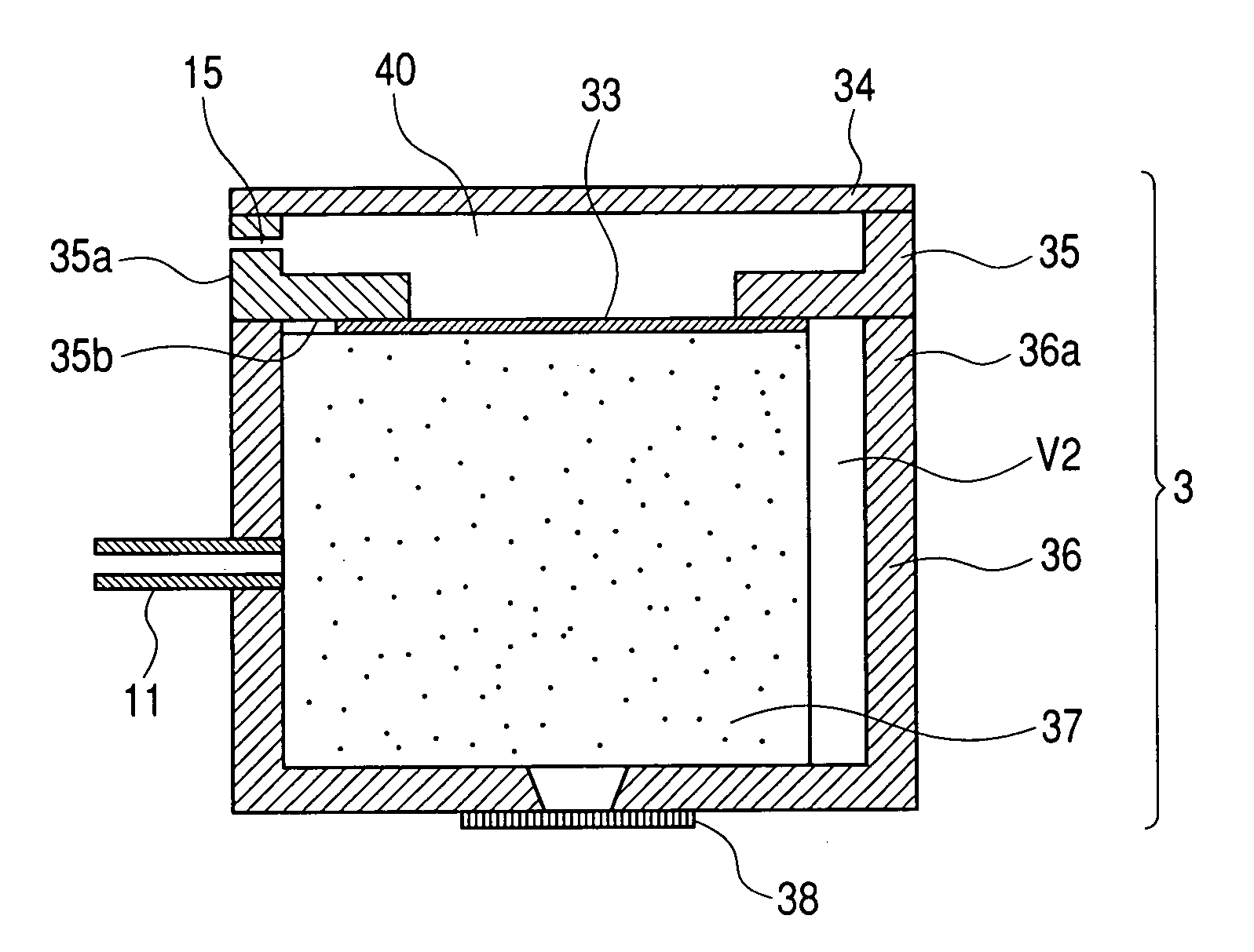
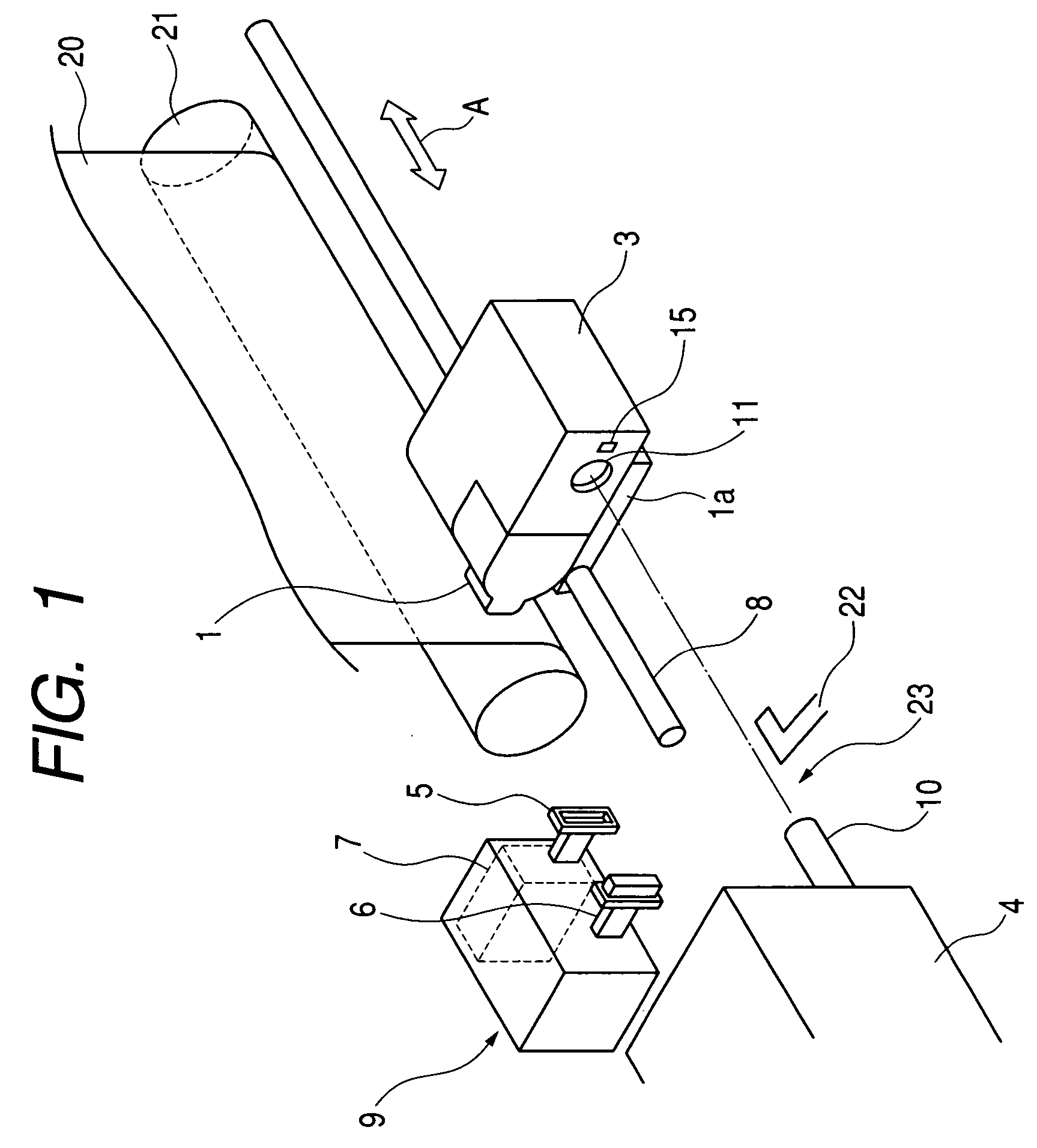
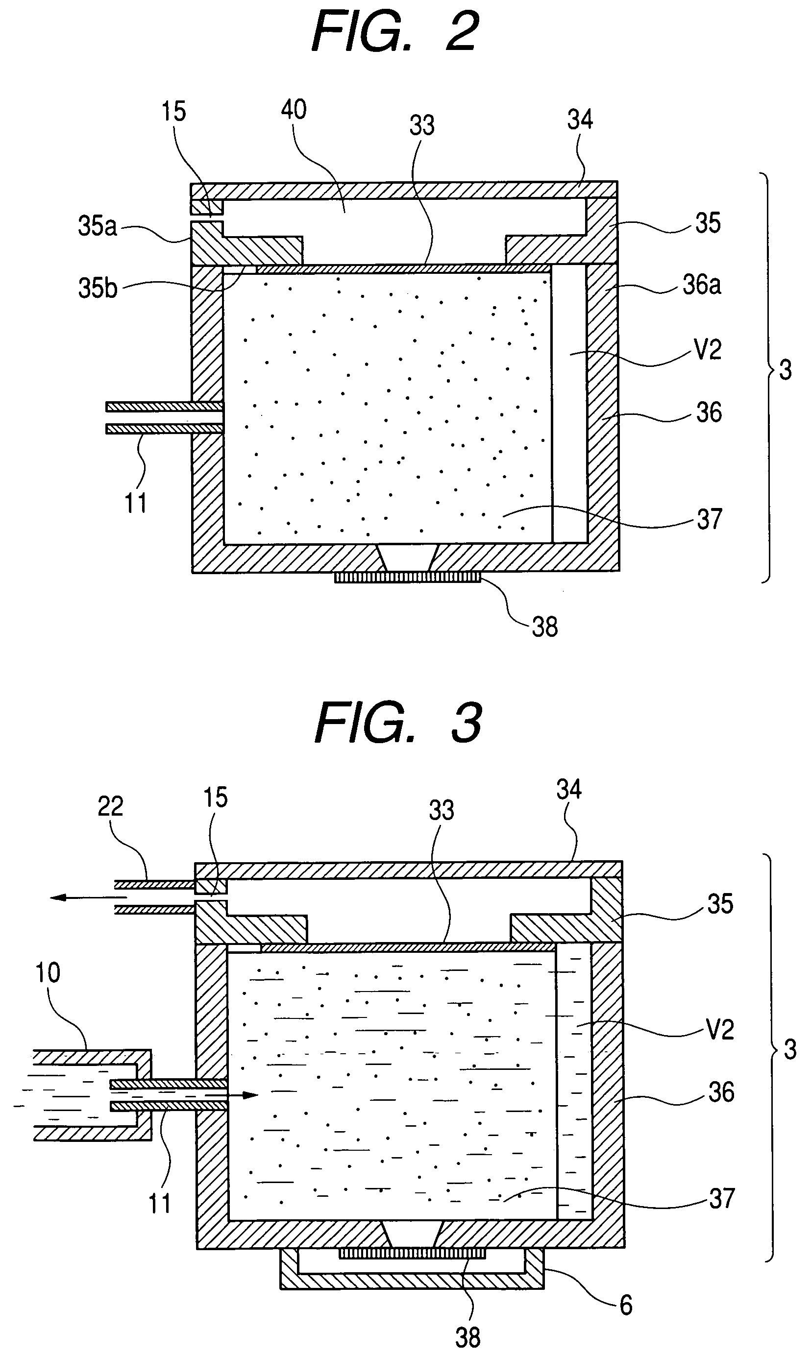
[0053]FIG. 1 is a partial schematic perspective view of a pit-in type ink jet recording apparatus in Embodiment 1 according to the present application. FIG. 2 is a side cross-sectional view of an ink jet recording head mounted in the ink jet recording apparatus shown in FIG. 1 and employing a gas-liquid separation member.

[0054]The ink jet recording apparatus in Embodiment 1 includes a carriage 1a mounting thereon an ink jet recording head 1 which discharges an ink to a recording sheet 20 carried by a paper feed roller 21 and which records data on the recording sheet 20, a main tank 4 storing an ink replenished into a sub-tank 3 of the ink jet recording head 1, and a recovery mechanism 9 which recovers an ink discharge characteristic of the ink jet recording head 1.

[0055]The carriage 1a mounting thereon the ink jet recording head 1 is guided by a guide shaft 8 and scanned forward and backward in an arrow A direction.

[0056]The main tank 4 is arranged at a home position 2...

embodiment 2

(Embodiment 2)

[0076]FIGS. 8A to 8C are side cross-sectional views of the ink jet recording head, illustrating examples of the ink absorbing member applied to the sub-tank in the ink jet recording head according to the present invention. The ink jet recording head in Embodiment 2 is equal in configuration as the ink jet recording head in Embodiment 1 except for the difference in the shape of the ink absorbing member. Therefore, the configuration of the ink jet recording head will not be described herein in detail and the same constituent members as those in Embodiment 1 are denoted by the same reference symbols, respectively.

[0077]An ink absorbing member 37a shown in FIG. 8A is shaped so that a second side surface 36b of the ink absorbing member 37a is cut aslant so as to form the space V2, in which the ink absorbing member 37a is not arranged, on a second side surface 36b on which the ink supply port 11 is provided.

[0078]An ink absorbing member 37b shown in FIG. 8B is shaped so that...

embodiment 3

(Embodiment 3)

[0081]FIG. 9 is a side cross sectional view of an ink jet recording head in Embodiment 3.

[0082]A sub-tank 103 of the ink jet recording head 101 in this embodiment is constituted so that an interior of an ink reservoir 136 is divided into three ink chambers 106, an ink supply section 103 is provided below each of the ink chambers 106, and that an ink absorbing member 137 stored in each ink chamber 106 is supplied to an ink jet recording element 138.

[0083]A cap member 135 and a cover member 134 are attached onto the ink reservoir 136. Communication sections 107 corresponding to the respective ink chambers 116 and an air hole 115 which communicates the interiors of the ink chambers 116 with the air are formed in the cap member 135. The cover member 134 is attached to the cap member 135, thereby forming a common communication path 117 which communicates the air hole 115 with the respective communication sections 107.

[0084]Each ink chamber 106 includes the ink absorbing mem...


PUM


Abstract

In a sub-tank of an ink jet recording head, an ink absorbing member capable of being impregnated with and holding an ink is arranged and a space V2, which is an area formed by a first wall surface of an ink reservoir and the ink absorbing member and in which the ink absorbing member is not present, is formed. A gas-liquid separation member made of a porous member, transmitting a gas but shutting off a liquid such as the ink is provided in a cap member in which an air hole is formed. A volume of the space V2 and a total volume V2 of an amount of the ink by which the ink is discharged from a discharge port of an ink jet recording element in one recovery operation and an initial pre-discharge amount hold a relationship of 0.7V1≦V2≦V1.

Description

BACKGROUND OF THE INVENTION[0001]1. Field of the Invention[0002]The present invention relates to an ink reservoir which stores an ink supplied to a recording head employed in an ink jet recording field, an ink jet head structure including the ink reservoir, and an ink jet recording apparatus including the ink reservoir. More specifically, the present invention relates to an ink jet head structure including an ink reservoir which structure adopts an intermittent ink supply system mounted on a carriage of the ink jet recording apparatus with an ink jet recording head, connected to a main ink tank at need and intermittently supplied with an ink and to an ink jet recording apparatus including the ink reservoir.[0003]2. Related Background Art[0004]As an ink jet recording apparatus that records data while scanning an ink jet recording head, there is known a so-called on-carriage type ink jet recording apparatus where an ink jet recording head 201 having a nozzle which discharges an ink is...

Claims


Application Information

Patent Timeline
Patent Type & Authority Patents(United States)
IPC IPC(8): B41J2/175
CPCB41J2/17509B41J2/17513B41J2/17556
Inventor TANIGUCHI, SUGURUUJITA, TOSHIHIKO
Owner CANON KK
Why Eureka
Try Eureka