
Adjustable gastric implant

a gastric implant and adjustable technology, applied in the field of gastric implants, can solve the problems of high rate of further surgery, frequent secondary complications, and inconvenient end portions for enabling the strap to be closed as a loop

Inactive Publication Date: 2005-11-22
MEDICAL INNOVATION DEV
View PDF8 Cites 353 Cited by
  • Summary
  • Abstract
  • Description
  • Claims
  • Application Information

AI Technical Summary

Problems solved by technology

That kind of surgery gives rise to frequent secondary complications involving a high rate of further surgery, even though statistics show that food tolerance is mediocre.
It can be considered that such a device makes it possible to satisfy the object of localized implantation and constriction of the stomach, but experience has shown up various drawbacks relating to such a device.
Firstly, its end portions for enabling the strap to be closed as a loop are not suitable for providing a band of regular shape approximating closely to an ideal circular section.
This gives rise to spot concentrations of stresses that subject the stomach wall to localized pressures which can give rise to intolerance phenomena, and even in some cases can be responsible for local puncturing.
In addition, the existence of a constriction band of internal section that is not regular is also unfavorable for defining a small-section passage suitable for establishing basically satisfactory transit.
It has also been found, in particular because of its method of manufacture, that an elongate strap that is flexible but not stretchable possesses edges running along its longitudinal sides which are sharp and consequently liable to injure the stomach wall.
It has even been found that these sharp edges can give rise to local puncturing which naturally requires corrective surgery to be performed very quickly.
It has also been found that, because of the sharp edges, connecting the strap and the bag together by means of adhesive can also lead to a risk of the inflated bag being punctured, thus preventing the bag from calibrating the channel and also being responsible for effusion of the inflation liquid, even though this liquid is generally of a physiological kind.
Finally, it should be observed that the nature of the means for interconnecting the end portions cause these means, once they have been connected together, to take up a diverging configuration like the open blades of a pair of scissors, and in this state, said end portions are then often responsible for damaging, irritating, or indeed puncturing the stomach wall.

Method used


Image

  • Adjustable gastric implant
  • Adjustable gastric implant
  • Adjustable gastric implant

Examples


Embodiment Construction

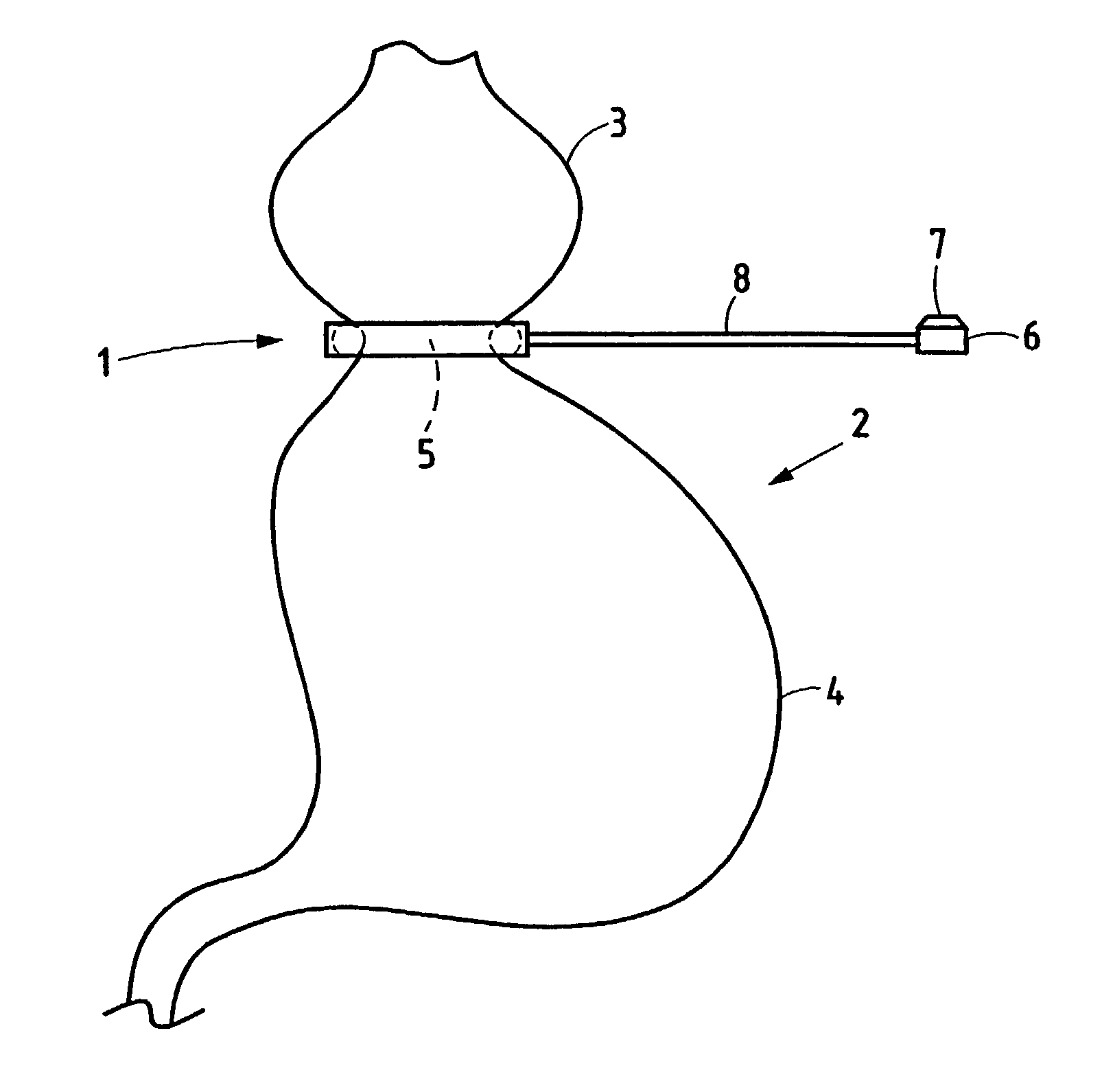
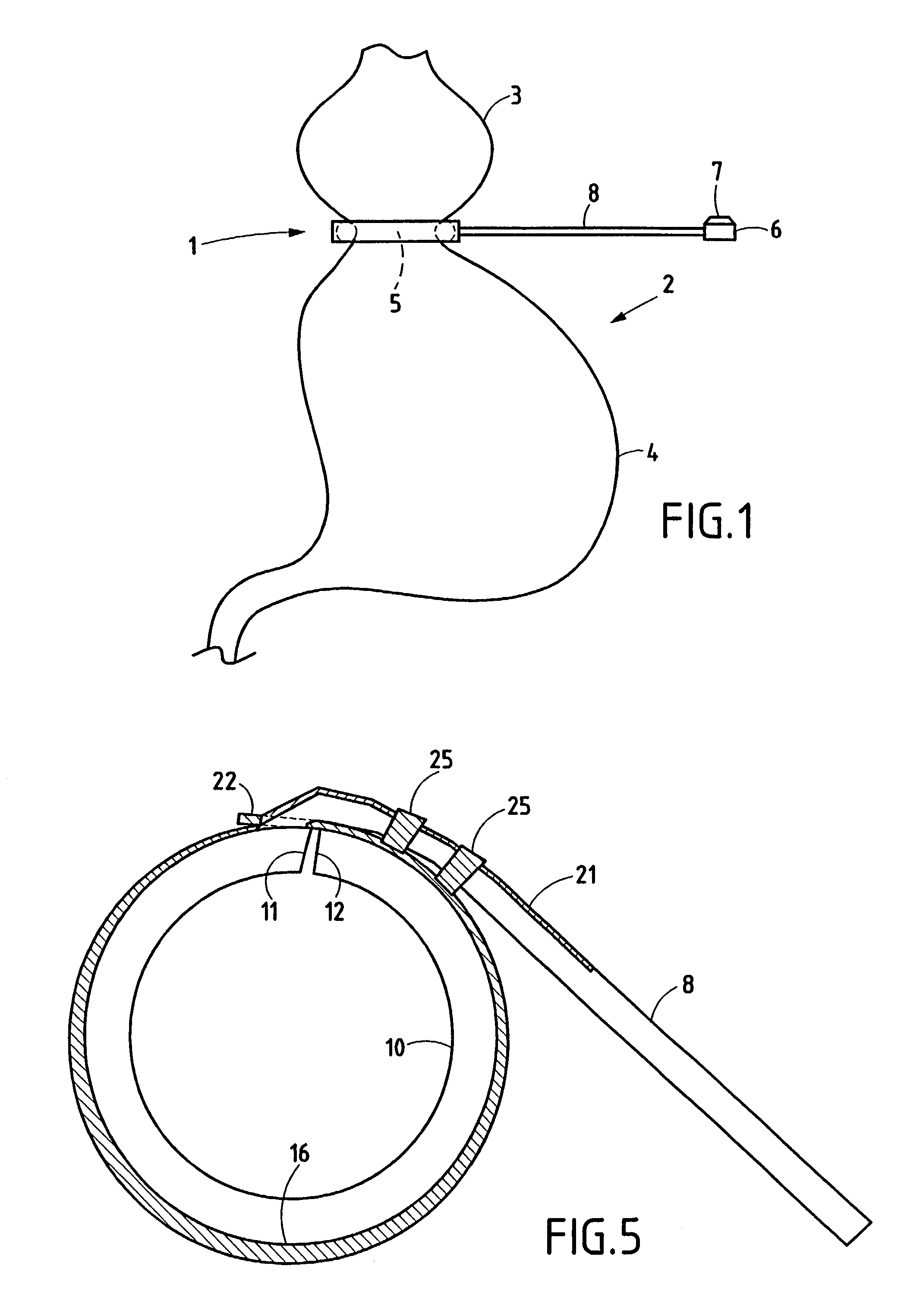
[0033]FIG. 1 is a diagram showing how a gastric band given reference 1 is implanted in a high, sub-hiatal position on a stomach 2 so as to define an artificial top gastric pocket 3 which is in communication with a bottom gastric pocket 4 via a communicating channel 5 of through section controlled by the gastric implant 1.

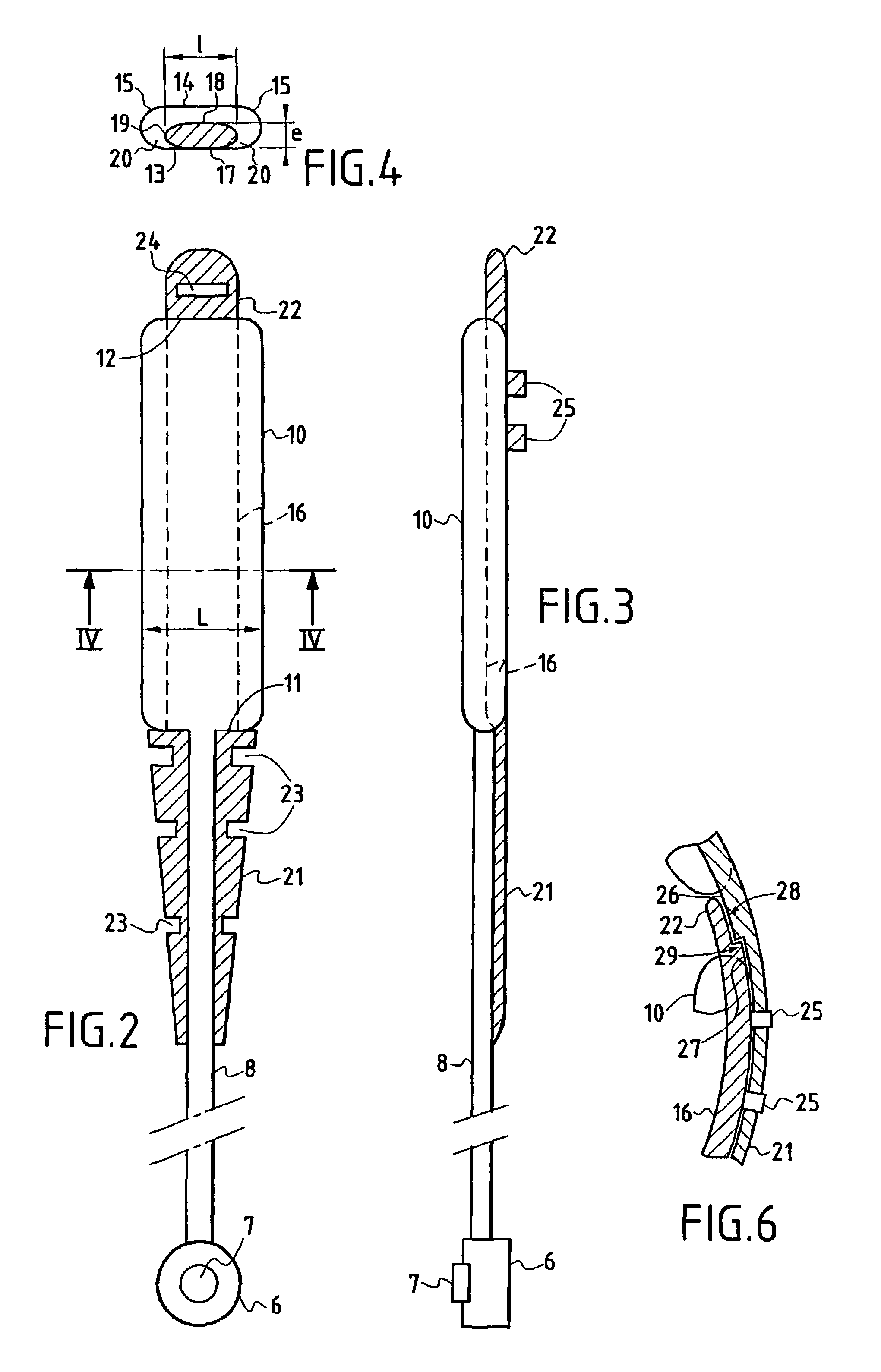
[0034]In a known disposition, the gastric implant 1 is constituted in the form of a closed-loop belt or hoop for generating constriction in the stomach wall by means of a bag that is inflatable with liquid, such as physiological serum, that is taken from or inserted into said bag by means of a box 6 possessing a self-sealing membrane 7 which can be pierced by means of the needle of a suitable syringe, or by analogous means. The box 6 is connected to the inflatable bag via a flexible tube 8 of length and flexibility selected to facilitate implantation of the box 6 under the skin. In accordance with the invention, the gastric implant 1 is characterized by a structure ...


PUM


Abstract

A gastric band implant characterized in that a strap constituted by an elongate piece is secured to the inside of an inflatable bag. The width and thickness of the piece are smaller than the corresponding dimensions of an oblong right cross-section of the bag. The piece possesses convex longitudinal edges and has complementary overlapping connection structures on opposite end portions of the strap.

Description

FIELD OF THE INVENTION[0001]The invention relates to the field of gastric implants which are fitted around the patient's stomach so as to define a pocket or cavity of relatively small volume in the upper portion thereof which communicates with the remainder of the stomach via a channel or duct which is calibrated by means of the implant.[0002]This field corresponds to a method of combating obesity and has been the subject of various technical proposals seeking to achieve local constriction that reduces the stomach's ability to absorb food by surgery acting locally on the stomach.DESCRIPTION OF RELATED ART[0003]Amongst known techniques, it is appropriate to mention the “by-pass” technique which consists in isolating an upper portion of the stomach by means of staples or the like and in connecting this portion to the outlet of the stomach via a by-pass. That technique is referred to by the term “gastric by-pass”.[0004]In reality, that method constitutes major surgery and can be consid...

Claims


Application Information

Patent Timeline
Patent Type & Authority Patents(United States)
IPC IPC(8): A61F5/00A61F2/02
CPCA61F5/005A61F5/0066
Inventor LONGOBARDI, BRUNO
Owner MEDICAL INNOVATION DEV
Learn More