
Recovery force adjustment device for a paddle of a cymbal stand

a recovery force and adjustment device technology, applied in the direction of instruments, percussion instruments, instruments, etc., can solve the problems of troublesome adjustment process and inefficiency of the recovery force magnitude adjustment process, and achieve the effect of easy adjustment of the recovery force magnitud

Inactive Publication Date: 2005-11-22
HSIEH WU HONG
View PDF3 Cites 3 Cited by
  • Summary
  • Abstract
  • Description
  • Claims
  • Application Information

AI Technical Summary

Benefits of technology

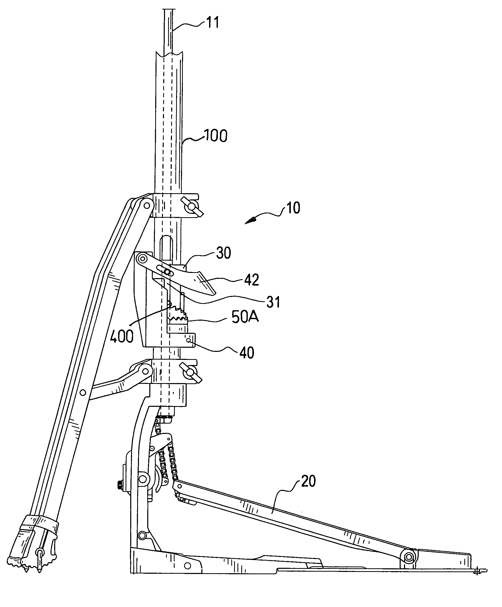
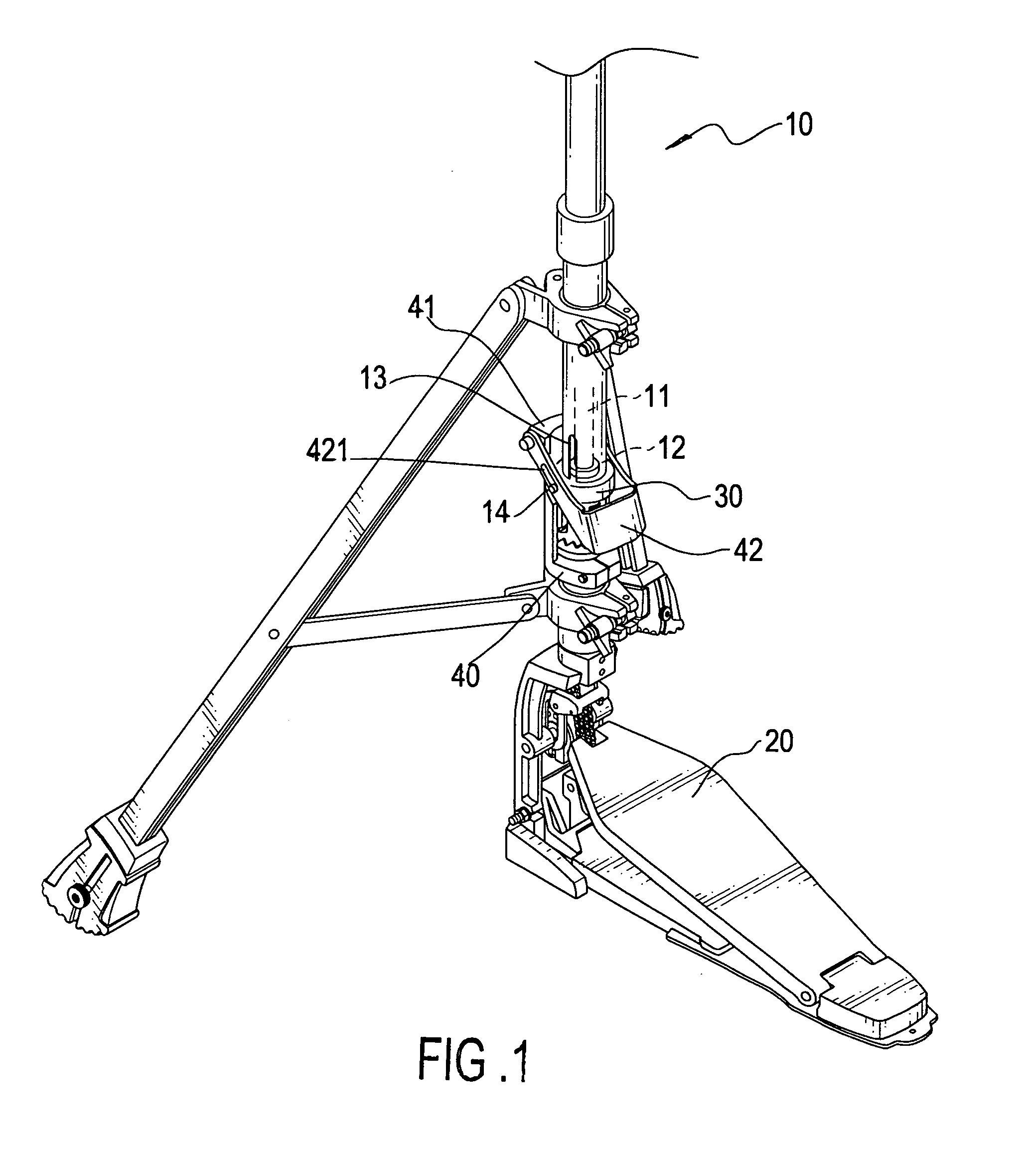
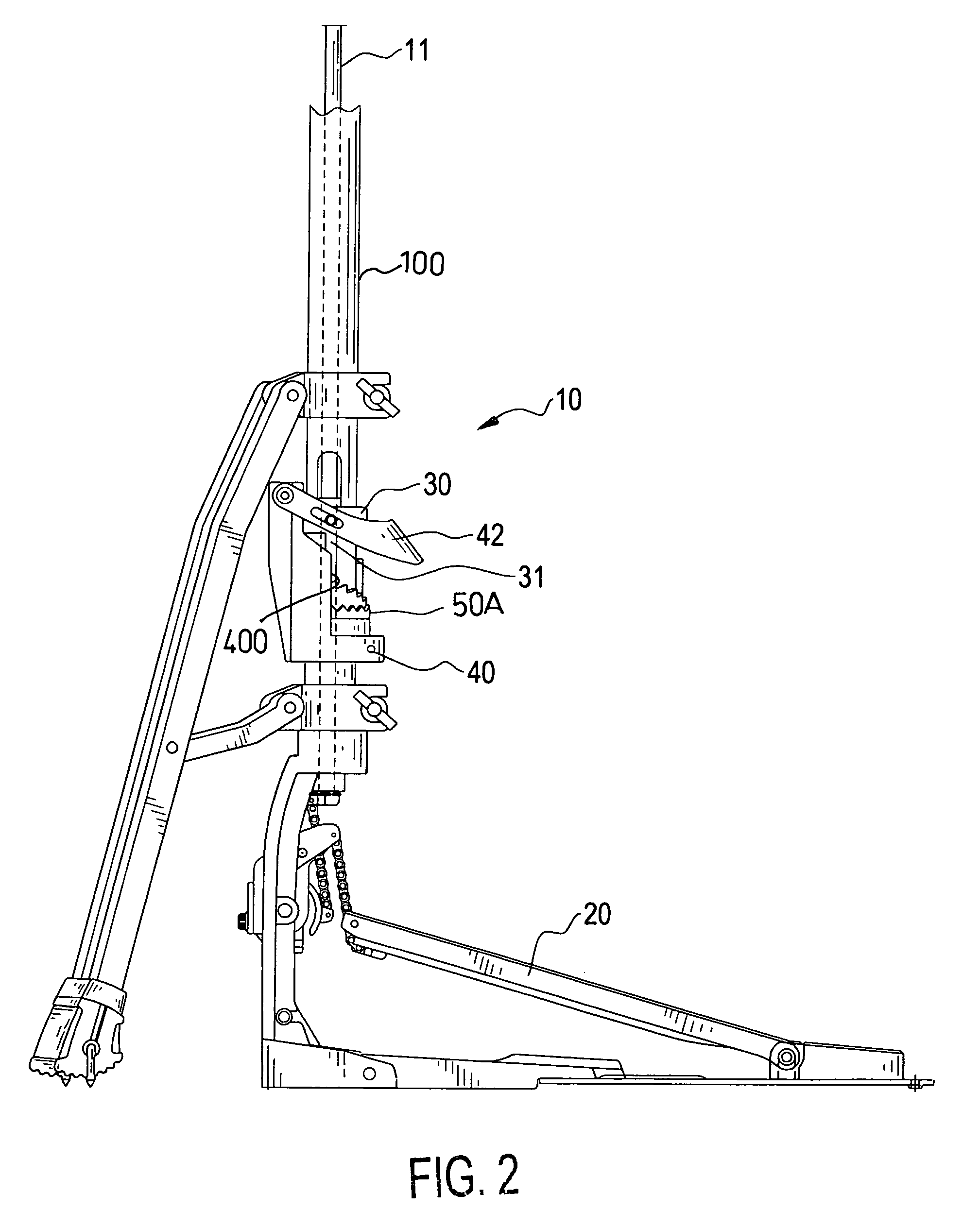
"The present invention provides an improved recovery force-adjusting device for a cymbal stand. It allows the user to easily adjust the magnitude of the recovery force from the recovery spring to the paddle of the cymbal stand. The device includes a handle pivotally mounted on the supporting seat of the cymbal stand, a driving ring movably mounted around a column of the cymbal stand and extending through the column, and a rotating sleeve rotatably mounted around the column. The driving ring has two extensions oppositely extending towards the rotating sleeve which has a set of first teeth, a set of second teeth, and a set of third teeth formed on the outer periphery of the rotating sleeve. The supporting seat has a wedge formed on its inner face to correspond to a tooth of the first set of teeth. When the two extensions are positioned in teeth of both the second and third sets of teeth, the wedge is on a slope of a tooth of the first set of teeth. When the handle is pivoted to force the wedge to be positioned in the tooth of the first set of teeth, the sliding movement of the wedge along the slope of the tooth of the first set of teeth forces the rotating sleeve to rotate, which allows the two extensions to correspond to and be received in different two teeth respectively of the second set of teeth and the third set of teeth. Thus the recovery force from the recovery spring is changed."

Problems solved by technology

That is, the adjustment process of the magnitude of the recovery force is troublesome and inefficient.

Method used


Image

  • Recovery force adjustment device for a paddle of a cymbal stand
  • Recovery force adjustment device for a paddle of a cymbal stand
  • Recovery force adjustment device for a paddle of a cymbal stand

Examples


Embodiment Construction

[0016]With reference to FIG. 1, a cymbal stand (10) has a paddle (20) movably connected to the cymbal stand (10) via a transmission rod (11) in a column (not numbered) such that a cymbal (not shown) on top of the transmission rod (11) is driven by the movement of the paddle (20). It is to be appreciated that the mechanism for the transmission rod (11) to resume its original position after movement of the paddle (20) is the spring (as shown in FIG. 3) which is mounted around the transmission rod (11). The spring has a first distal end securely connected to the paddle (20) and a second distal end securely connected to a stop movably received in the column and mounted outside the transmission rod (11). Because the recovery mechanism of the cymbal stand (10) is conventional in the art, detailed description of the interaction of the paddle (20) and the recovery spring, as well as the stop is omitted for brevity.

[0017]With reference to FIGS. 2 and 3, the recovery force adjusting device in...


PUM


Abstract

A recovery force adjusting device for a cymbal stand includes a handle, a driving ring movable relative to the column and having a pin extending through the stop, a supporting seat having a cutout and a wedge the supporting seat, a rotating sleeve rotatably and movably sandwiched between the supporting seat and the driving seat and having a first, a second and a third sets of teeth formed on the rotating sleeve and a recovery spring to move the rotating sleeve upward. Due to the misalignment relationship between the wedge and the tooth of the first set of teeth, sliding movement of the wedge along a slope of the corresponding tooth of the first set of teeth forces the rotating sleeve to rotate and thus the position of the driving ring is changed. A compression force to the spring is thus adjusted.

Description

BACKGROUND OF THE INVENTION[0001]1. Field of the Invention[0002]The present invention relates to a recovery force adjustment device, and more particularly to a recovery force adjustment device for a paddle of a cymbal stand so that the user is able to easily adjust the magnitude of the paddle recovery force to adapt to different performers with different habits[0003]2. Description of Related Art[0004]With reference to FIG. 7, a conventional adjusting device for changing the magnitude of the recovery force from the transmission rod (50) to the paddle (60) of a cymbal stand (70) includes a bonding block (53) securely connecting the first rod (51) to the second rod (52) of the transmission rod (50), a stop (54) formed on a mediate portion of the first rod (51) and having a disk (56) extending from the stop (54) and a recovery spring (55) mounted around the first rod (51) and sandwiched between the disk (56) and the bonding block (53). A sleeve (57) is screwingly connected to the outer ...

Claims


Application Information

Patent Timeline
Patent Type & Authority Patents(United States)
IPC IPC(8): G10D13/00G10D13/02G10D13/06
CPCG10D13/065
Inventor HSIEH, WU-HONG
Owner HSIEH WU HONG
Learn More