Yaw rate sensor and method for operating a yaw rate sensor

a sensor and yaw rate technology, applied in the direction of acceleration measurement using interia force, turn-sensitive devices, instruments, etc., can solve the problems of disadvantageous change of quadrature, overload of detection branches, unwanted offset signals in detection branches, etc., and achieve the effect of sufficient high basic modulation amplitud

Active Publication Date: 2013-04-02
ROBERT BOSCH GMBH
View PDF5 Cites 4 Cited by
  • Summary
  • Abstract
  • Description
  • Claims
  • Application Information

AI Technical Summary

Benefits of technology

[0004]The yaw rate sensor according to the exemplary embodiments and / or exemplary methods of the present invention and the method according to the present invention for operating a yaw rate sensor according to the independent claims have the advantage over the related art that an active excitation of the 2f quadrature interference signal is made possible. The magnitude of the 2f quadrature interference signal may, in particular, be advantageously variably set and adjusted, so that the yaw rate sensor may be continuously optimized with regard to its modulation amplitude independently of external influences or manufacturing-related imperfections. In particular, it is thus possible to set a sufficiently high basic modulation amplitude without the danger of overload. This is achieved by the fact that the yaw rate sensor according to the present invention, in contrast to the related art, has an interference element which is provided to actively excite the Coriolis element to interference oscillation, so that, in particular, an active excitation of the 2f quadrature interference signal is achieved.
[0006]According to a specific embodiment, it is provided that the interference element has a fixed electrode connected to the substrate which is situated in a recess of the Coriolis element parallel to the main plane of extension. The interference oscillation is thus advantageously excitable by a direct electrostatic interaction between the Coriolis element and the fixed electrode, it being possible to easily set the magnitude of the interference oscillation, i.e., in particular the amplitude of the interference oscillation, by applying an appropriate potential difference between the fixed electrode and the Coriolis element.
[0008]According to a specific embodiment, it is provided that the interference oscillation has a frequency which is essentially twice the frequency of the driving oscillation, and / or it is provided that the interference oscillation is parallel to the driving oscillation. A 2f quadrature interference signal is thus advantageously excited, so that the modulation amplitude of the yaw rate sensor may be optimally adjusted.
[0009]According to a specific embodiment, it is provided that the yaw rate sensor includes compensation elements for exciting compensation forces, the compensation elements including, in particular, compensation electrodes connected to the substrate, each of which is situated in compensation recesses of the Coriolis element on the main plane of extension, the compensation recesses may have an L-shaped and / or S-shaped design, and the compensation forces may have a frequency which is essentially equal to the frequency of the driving oscillation. A compensation of the 1f quadrature interference signal is thus advantageously achieved, whereby an offset is suppressed in the detection branch and this compensation is not needed for setting the modulation amplitude of the yaw rate sensor.

Problems solved by technology

The compensation structures are provided to compensate a 1f quadrature interference signal which is generated by manufacturing-related imperfections in the sensor structure and which result in modulation of the detection signals at the driving frequency and thus result in unwanted offset signals in the detection branch.
Furthermore, there is a 2f quadrature interference signal whose frequency is double the frequency of the oscillation and may result in overload in the detection branch.
The quadrature is disadvantageously changed by external influences (for example, by temperature changes or substrate bending due to package stress), while the dimensioning of the coupling spring is not adjustable later, in particular during operation of the yaw rate sensor.
Consequently, it is not practical to modify the 2f quadrature interference signal by suitably dimensioning the coupling spring.
Moreover, a complete suppression of the 2f quadrature interference signal results in the yaw rate sensor having too low a basic modulation amplitude, which impairs the functionality of the yaw rate sensor, in particular at low yaw rates.

Method used


Image

  • Yaw rate sensor and method for operating a yaw rate sensor
  • Yaw rate sensor and method for operating a yaw rate sensor
  • Yaw rate sensor and method for operating a yaw rate sensor

Examples


Embodiment Construction

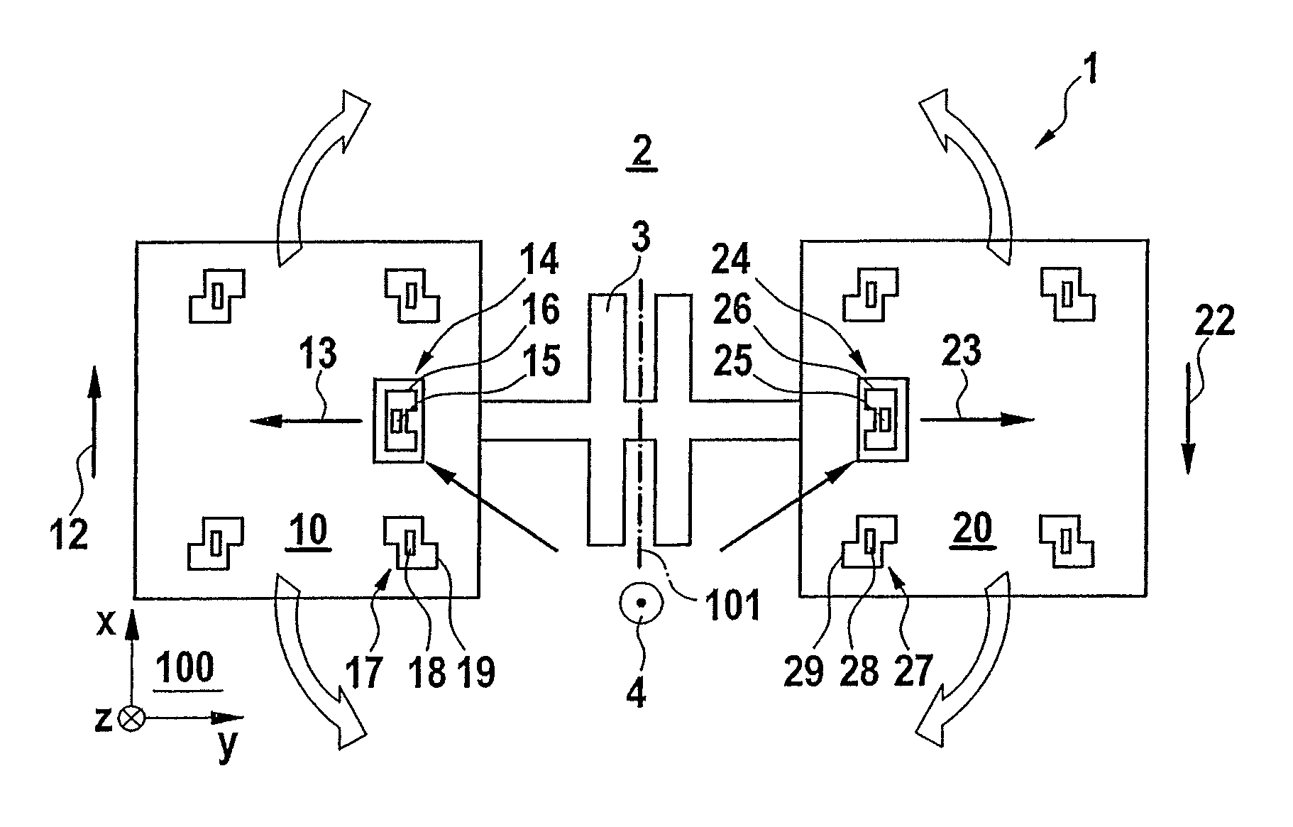
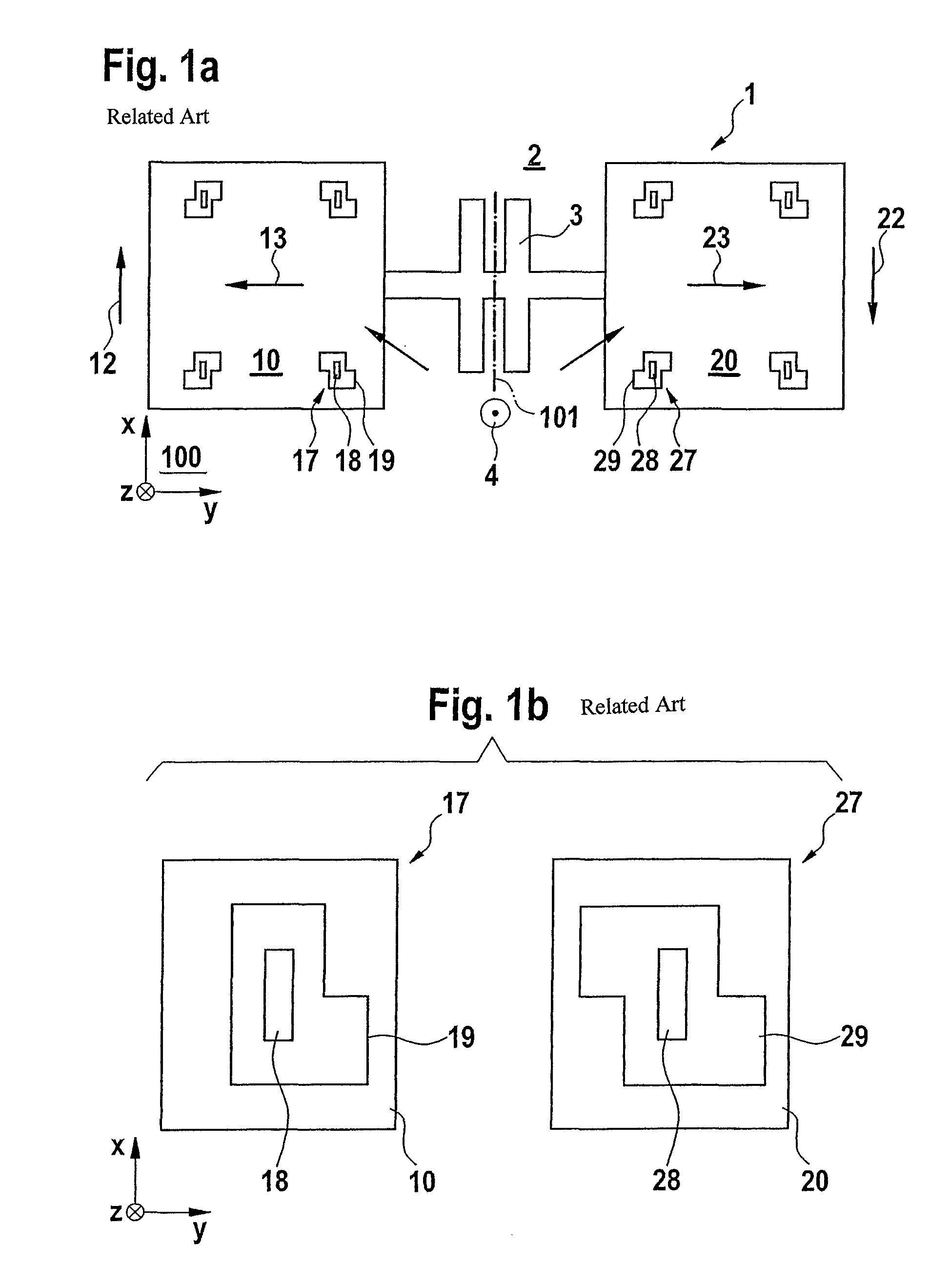
[0022]FIG. 1a shows a schematic top view of a yaw rate sensor 1 according to the related art, yaw rate sensor 1 including a Coriolis element 10 and a further Coriolis element 20, which are coupled to each other by an elastic element 4. Coriolis element 10 is excited to a driving oscillation 12 parallel to a first direction X by a driving arrangement (not illustrated), first direction X running parallel to a main plane of extension 100 of a substrate 2. Further Coriolis element 20 is driven to a further driving oscillation 22, which is antiparallel to driving oscillation 12, using a further driving arrangement (not illustrated). In the presence of a yaw rate 4 around a rotation axis parallel to a third direction Z, third direction Z being perpendicular to first direction X and perpendicular to main plane of extension 100, a Coriolis force acts upon Coriolis element 10 along second direction Y, which is perpendicular to first and third directions X, Y, so that Coriolis element 10 unde...


PUM


Abstract

A yaw rate sensor is described which includes a substrate having a main plane of extension and a Coriolis element, the Coriolis element being excitable to a driving oscillation along a first direction parallel to the main plane of extension, using a driving arrangement, and a deflection of the Coriolis element along a second direction perpendicular to the first direction being detectable, and the yaw rate sensor having an interference element for exciting the Coriolis element to an interference oscillation.

Description

RELATED APPLICATION INFORMATION[0001]The present application claims priority to and the benefit of German patent application no. 10 2009 028 623.3, which was filed in Germany on Aug. 18, 2009, the disclosure of which is incorporated herein by reference.FIELD OF THE INVENTION[0002]The present invention is directed to a yaw rate sensor.BACKGROUND INFORMATION[0003]Yaw rate sensors of are believed to be generally understood. For example, a yaw rate sensor is discussed in International patent publication WO 03 / 058 167 A1, which includes a substrate and two Coriolis elements, the Coriolis elements being excitable to antiparallel oscillations parallel to the substrate along a first axis X so that, in the presence of a yaw rate perpendicular to the substrate along a third direction Z, antiparallel deflections of the Coriolis elements, which are detectable for determining the yaw rate, are generated along a second direction Y perpendicular to both the first direction X and the third directio...

Claims


Application Information

Patent Timeline
Patent Type & Authority Patents(United States)
IPC IPC(8): G01C19/56G01C19/574
CPCG01C19/574
Inventor PRUETZ, ODD-AXEL
Owner ROBERT BOSCH GMBH
Why Eureka
Try Eureka