Power Supply Device

a power supply device and power supply technology, applied in the direction of electric variable regulation, process and machine control, instruments, etc., can solve the problems user cannot know the magnitude of the voltage inputted to the power supply device, etc., to achieve the effect of reducing output or efficiency of the power supply device and easily checking the magnitude of the input voltag

Active Publication Date: 2020-02-13
ORMON CORP
View PDF11 Cites 2 Cited by
  • Summary
  • Abstract
  • Description
  • Claims
  • Application Information

AI Technical Summary

Benefits of technology

[0004]At a manufacturing location, for example, interconnections (a plurality of power-supply lines) for different power-supply voltages may be laid. If a power supply device meant for a certain power-supply line (e.g. a line for AC of 230 V) is connected to a power-supply line for a lower voltage (e.g. a line for AC of 115 V), the output or efficiency of the power supply device may reduce.
[0005]An object of the present invention is to provide a power supply device that enables the user to easily check the magnitude of the input voltage.

Problems solved by technology

The user, however, cannot know the magnitude of voltage inputted to the power supply device.
If a power supply device meant for a certain power-supply line (e.g. a line for AC of 230 V) is connected to a power-supply line for a lower voltage (e.g. a line for AC of 115 V), the output or efficiency of the power supply device may reduce.

Method used


Image

  • Power Supply Device
  • Power Supply Device
  • Power Supply Device

Examples


Embodiment Construction

[0017]An embodiment is hereinafter described in detail with reference to the drawings. In the drawings, identical reference numerals or characters denote identical or corresponding parts.

Application

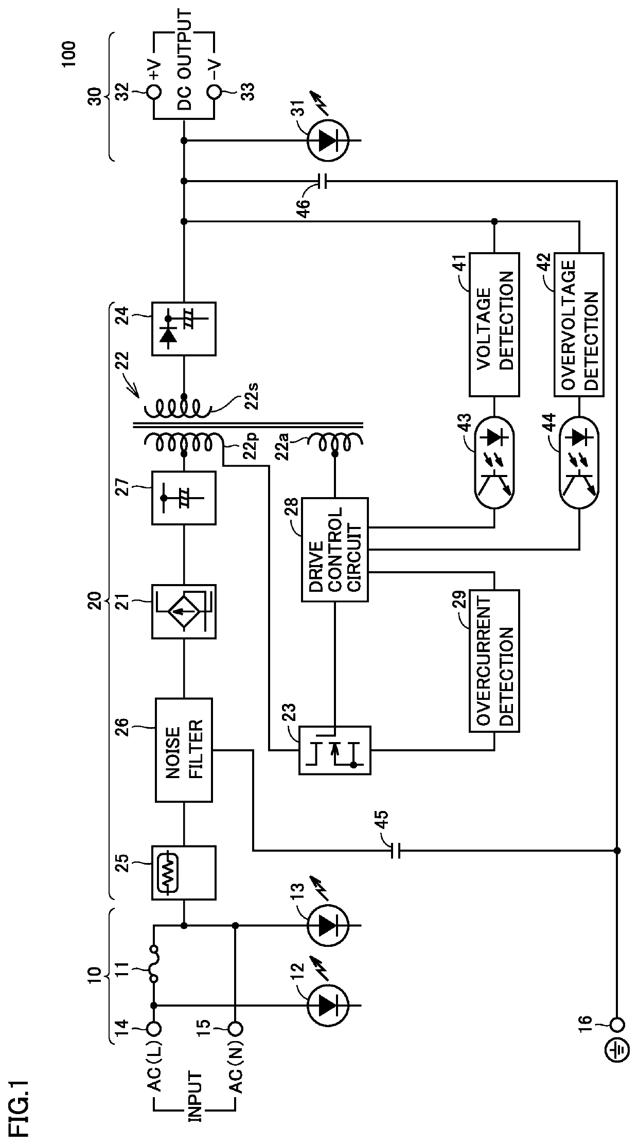
[0018]First of all, one example situation to which the present invention is applicable is described with reference to FIG. 1. FIG. 1 is a block diagram showing one configuration example of a power supply device 100 according to an embodiment. As shown in FIG. 1, power supply device 100 is, for example, a switching power supply device. Power supply device 100 includes an input unit 10 to receive an input voltage from outside, a power supply unit 20, and an output unit 30.

[0019]For example, input unit 10 is connected to an AC power supply (e.g. a commercial power supply with 50 Hz / 60 Hz, 100 V / 200 V) 1. Input unit 10 includes input terminals 14, 15 (also denoted by “INPUT”), a fuse 11 which is a protective circuit connected to input terminal 14, and a protective earth terminal 16.

[0020]Powe...


PUM


Abstract

A power supply device includes: an input unit configured to receive an input voltage from outside; a power supply unit configured to generate a power-supply voltage from the input voltage inputted through the input unit; an output unit including an output terminal configured to output the power-supply voltage; and a lighting circuit connected to the input unit and configured to be turned on in response to application of the input voltage. The lighting circuit is configured to vary in lighting mode depending on the input voltage.

Description

BACKGROUND OF THE INVENTIONField of the Invention[0001]The present invention relates to a power supply device.Description of the Background Art[0002]For example, Japanese Patent Laying-Open No. 2006-349626 discloses an implementation circuit that can detect a drop in supply of power-supply voltage. The implementation circuit includes an LED device for monitoring the status of the power-supply voltage, and a lighting control circuit for the LED device. When the power-supply voltage is equal to or more than a prescribed voltage, the lighting control circuit turns on the LED device. When the power-supply voltage is not equal to or more than the prescribed voltage, the lighting control circuit turns off the LED device.SUMMARY OF THE INVENTION[0003]According to the above-described configuration, the power supply device can notify the user of whether or not a voltage is being inputted to the power supply device. The user, however, cannot know the magnitude of voltage inputted to the power...

Claims


Application Information

Patent Timeline
Patent Type & Authority Applications(United States)
IPC IPC(8): H05B33/08H02M3/335H05B44/00H05B45/50
CPCH05B45/50H02M3/33523H05B45/37H02M1/00H05B45/44H05B45/382H05B45/40
Inventor NAGANO, MASAAKI
Owner ORMON CORP
Why Eureka
Try Eureka