Tactile feedback for cursor control device

a cursor control and tactile technology, applied in the field of tactile feedback for cursor control devices, can solve the problems of unsatisfactory and provide any tactile

Inactive Publication Date: 2005-11-22
MINEBEA CO LTD
View PDF21 Cites 18 Cited by
  • Summary
  • Abstract
  • Description
  • Claims
  • Application Information

AI Technical Summary

Problems solved by technology

Because a mouse is used in a position physically remote from the computer, it is not the preferred cursor control device for portable or laptop computers.
However, the pointing stick of Seffernick does not provide any tactile feedback to the user indicating that a click has occurred and is therefore not ideal.

Method used


Image

  • Tactile feedback for cursor control device
  • Tactile feedback for cursor control device
  • Tactile feedback for cursor control device

Examples


Embodiment Construction

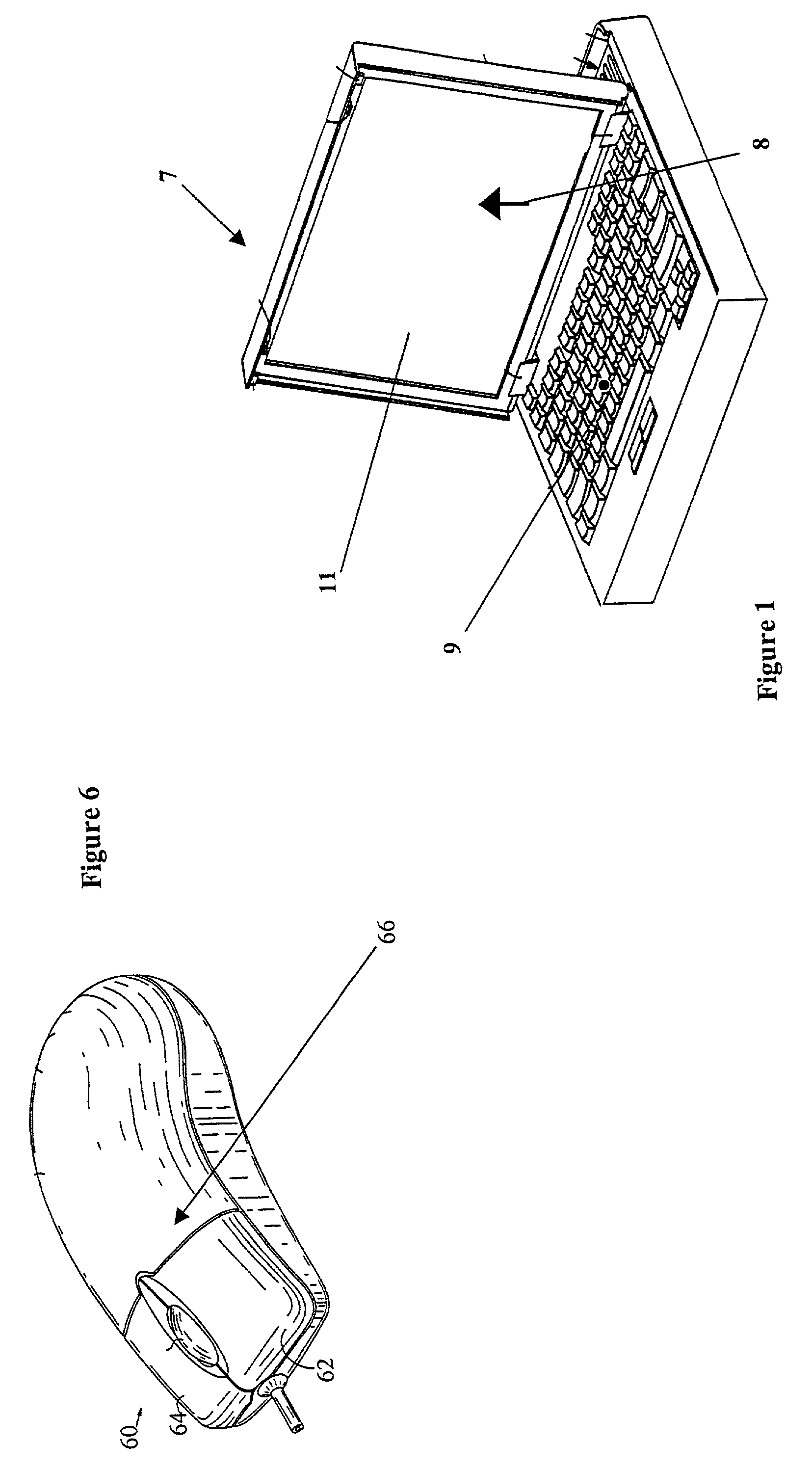
[0010]Computers typically are controlled by users through the use of various input control devices including a cursor control and keyboard. Computer 7 typically has a program running thereon that provides for movement of a cursor 8 on display device 11 in response to the user operating cursor control device 9. One such program is Microsoft Windows 98. Display device 11 can be any of a number of different devices, such as an LCD attached to a laptop computer; other similar devices such as a computer monitor employing a cathode ray tube (CRT) may also be used. Cursor control device 9 as shown in FIG. 1 is a pointing stick, although the invention is not limited to any particular pointing device. For example, cursor control device 9 may also be a mouse, joystick, wheel, trackball, or a touch pad. As shown in FIG. 1, cursor control device 9 is a pointing stick mounted between the “g”“h” and “b” keys on a standard “QWERTY” keyboard.

[0011]Cursor control device 9 allows a computer user to m...


PUM


Abstract

An apparatus for providing a tactile feedback to a user of a computer cursor control device such as a pointing stick is provided. A pzt material is first mounted to a semi-rigid material such as by bonding the pzt material to a metal substrate. When an ac signal is applied to this assembly it vibrates. By coupling this mechanical vibration to the pointing stick, the user can sense the feedback. This can be used, for example, to provide a tactile feedback when the user depresses the pointing stick to cause a “mouse click.”

Description

BACKGROUND OF THE INVENTION[0001]Computers use various cursor control mechanisms to provide a physical control over cursor placement on the computer screen. The most common form of cursor control device is a mouse. The mouse includes a plurality of buttons to allow the user to select various items on the screen. When the user depresses the mouse button, the switch inside provides a tactile feedback to the user commonly referred to as a “mouse click.”[0002]Because a mouse is used in a position physically remote from the computer, it is not the preferred cursor control device for portable or laptop computers. In these computers, users want the freedom to operate the computer without any additional external devices. One frequently used cursor control mechanism incorporated into portable computers is that of a pointing stick. These devices have been described in many patents including U.S. Pat. No. 5,966,117 to Seffernick incorporated herein by reference. The Seffernick device provides ...

Claims


Application Information

Patent Timeline
Patent Type & Authority Patents(United States)
IPC IPC(8): G06F1/16G06F3/00G06F3/033G06F3/01
CPCG06F1/1616G06F1/169G06F3/016G06F3/0338G06F2203/015
Inventor TICHY, THOMAS HENRYSTEINBRUNNER, STEVEN L.
Owner MINEBEA CO LTD
Why Eureka
Try Eureka