

Head suspension for disk drive
a technology for disc drives and suspensions, applied in the direction of magnetic recording, data recording, instruments, etc., can solve the problems of complex processes and frequent suspensions of head suspensions, and achieve the effect of suppressing the flexure fluttering
- Summary
- Abstract
- Description
- Claims
- Application Information
AI Technical Summary
Benefits of technology
Problems solved by technology
Method used
Image

Examples
first embodiment
[0046](First Embodiment)
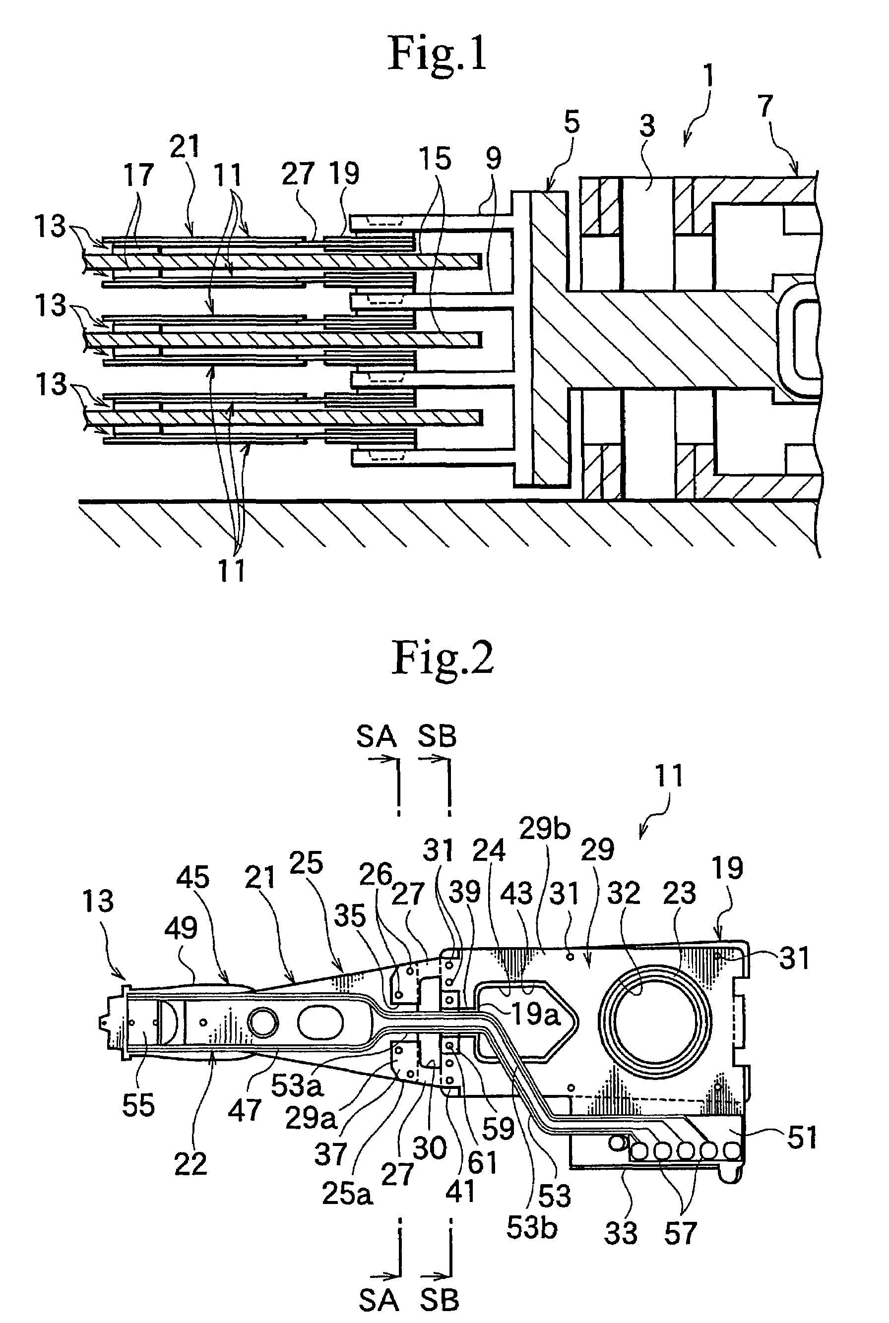
[0047]FIG. 1 is a sectional view partly showing a hard disk drive employing head suspensions according to the first embodiment of the present invention. The hard disk drive 1 has a carriage 5 to be turned around a spindle 3.
[0048]The carriage 5 is driven around the spindle 3 by a positioning motor 7 such as a voice coil motor. The carriage 5 has a plurality (four in FIG. 1) of carriage arms 9. Each carriage arm 9 has the head suspension 11 at a front end thereof. A front end of the head suspension 11 has a head 13. The carriage 5 is turned around the spindle 3, to move the head 13 to a target track on a disk 15.
[0049]The head 13 is used to write and read data to and from the disk 15 and includes a slider 17 facing tracks on the disk 15 and a transducer (not shown) supported with the slider 17. When the disk 15 is rotated at high speed, air enters between the disk 15 and the slider 17 to slightly float the slider 17 from the disk 15 and form an air bearing bet...
second embodiment
[0080](Second Embodiment)
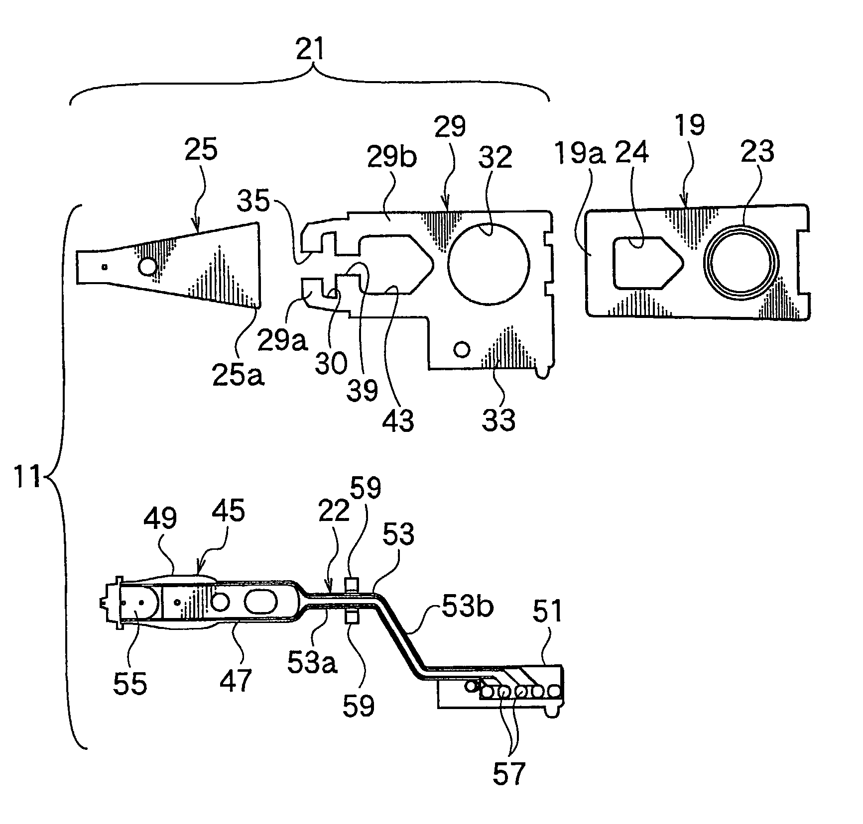
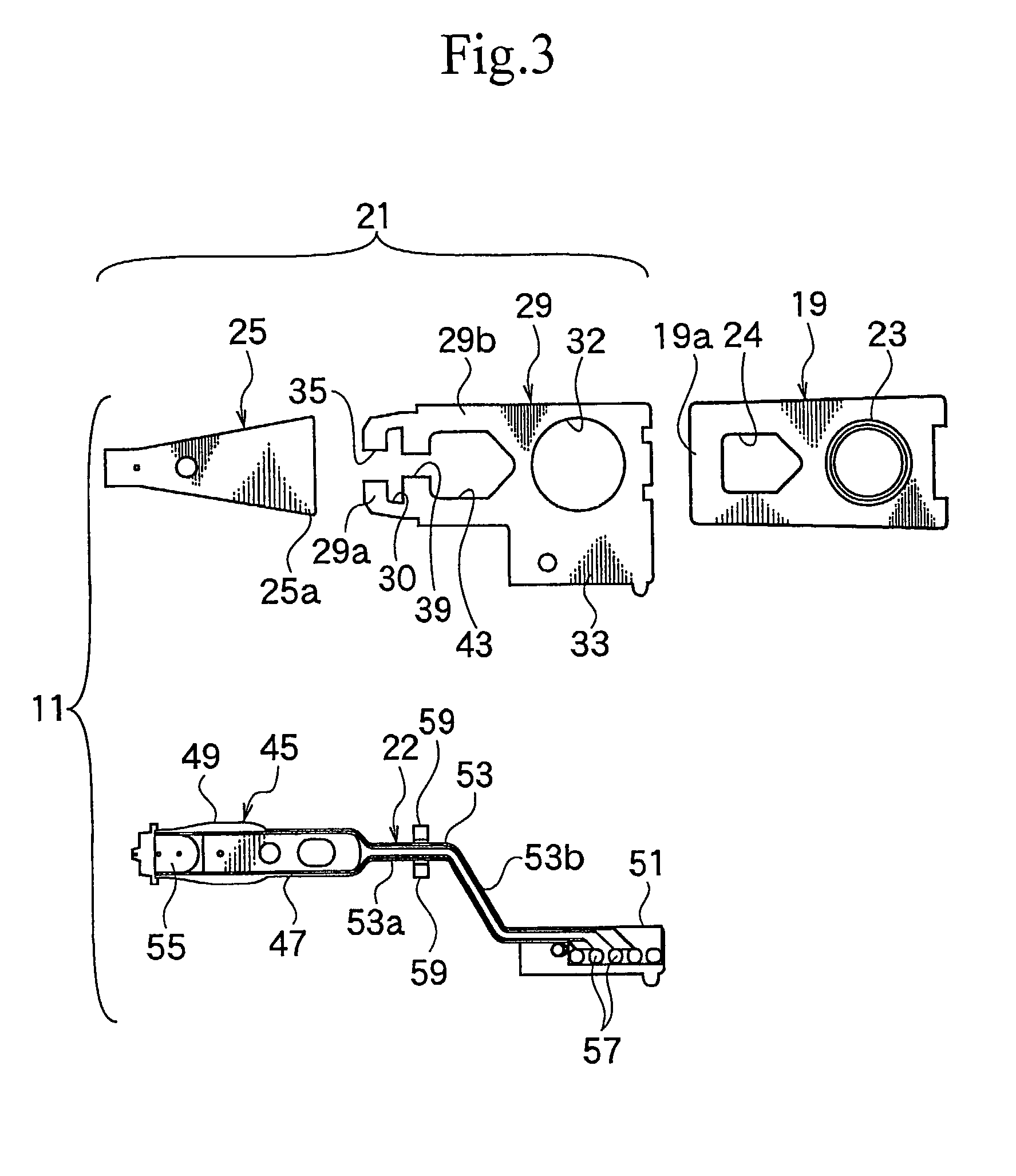
[0081]FIG. 7 is a plan view showing a head suspension 11A according to the second embodiment of the present invention seen from a flexure side, FIG. 8 is a plan view showing a resilient material 29A according to the second embodiment, and FIG. 9 is a sectional view taken along a line SC—SC of FIG. 7. The second embodiment is basically the same as the first embodiment, and therefore, parts corresponding to those of the first embodiment are represented with like reference numerals.
[0082]The second embodiment forms a second cut 39A of the resilient material 29A wider than the second cut 39 of the first embodiment. The width of the second cut 39A is determined according to a tip-to-tip distance of fixing pieces 59A of a flexure 22. The fixing pieces 59A flatly protrude from a metal base 45 of the flexure 22 and are secured to an end 19a of a plate 19.
[0083]In FIGS. 7 and 9, the fixing pieces 59A are received in the second cut 39A and are fixed to the end 19a of ...
third embodiment
[0092](Third Embodiment)
[0093]FIG. 10 is a plan view showing a head suspension 11B according to the third embodiment of the present invention seen from a flexure side, FIG. 11 is a plan view showing a resilient material 29B according to the third embodiment, andFIG. 12 is a sectional view taken along a line SD—SD of FIG. 10. The third embodiment is basically the same as the first embodiment, and therefore, parts corresponding to those of the first embodiment are represented with like reference numerals.
[0094]According to the third embodiment, the resilient material 29B has a continuous part 63 instead of the second cuts 39 and 39A of the first and second embodiments. Adjacent to the continuous part 63, there is a through hole 65 corresponding to a window 24 of a plate 19. Fixing pieces 59B flatly protrude from a metal base 45 of a flexure 22 and are tightly attached to the continuous part 63 of the resilient material 29B. In FIG. 10, the fixing pieces 59B are fixed to the continuous...
PUM
 Abstract
Description
Claims
Application Information