Shock actuated responsive mechanism with improved dual safety means to prevent over-rotation of the valve reset mechanism and to provide easy access to the reset knob

Inactive Publication Date: 2005-11-29
PACIFIC SEISMIC PRODS
View PDF6 Cites 29 Cited by
  • Summary
  • Abstract
  • Description
  • Claims
  • Application Information

AI Technical Summary

Benefits of technology

[0008]One object of the invention is to improve reliability of the closure of a fluid valve when specified shock and vibration forces are sensed by

Problems solved by technology

These non-actuating motions of the ball delay valve closure which may i

Method used


Image

  • Shock actuated responsive mechanism with improved dual safety means to prevent over-rotation of the valve reset mechanism and to provide easy access to the reset knob
  • Shock actuated responsive mechanism with improved dual safety means to prevent over-rotation of the valve reset mechanism and to provide easy access to the reset knob
  • Shock actuated responsive mechanism with improved dual safety means to prevent over-rotation of the valve reset mechanism and to provide easy access to the reset knob

Examples


Example

[0064]Although specific embodiments of the present invention will now be described with reference to the drawings, it should be understood that such embodiments are by way of example only and merely illustrative of but a small number of the many possible specific embodiments which can represent applications of the principles of the present invention. Various changes and modifications obvious to one skilled in the art to which the present invention pertains are deemed to be within the spirit, scope and contemplation of the present invention as further defined in the appended claims.

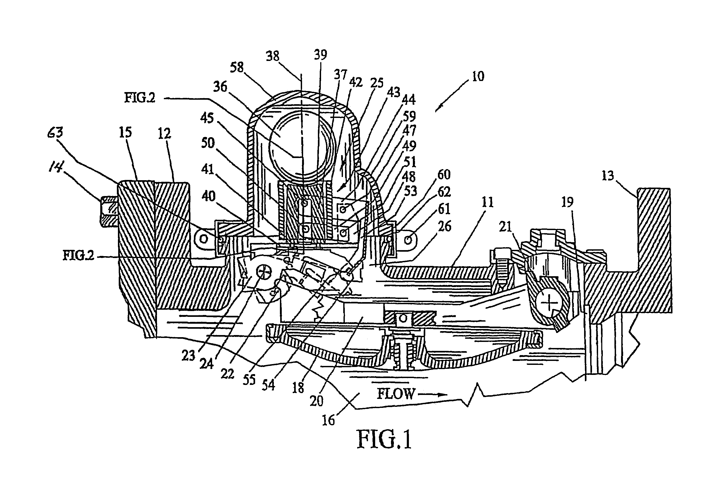
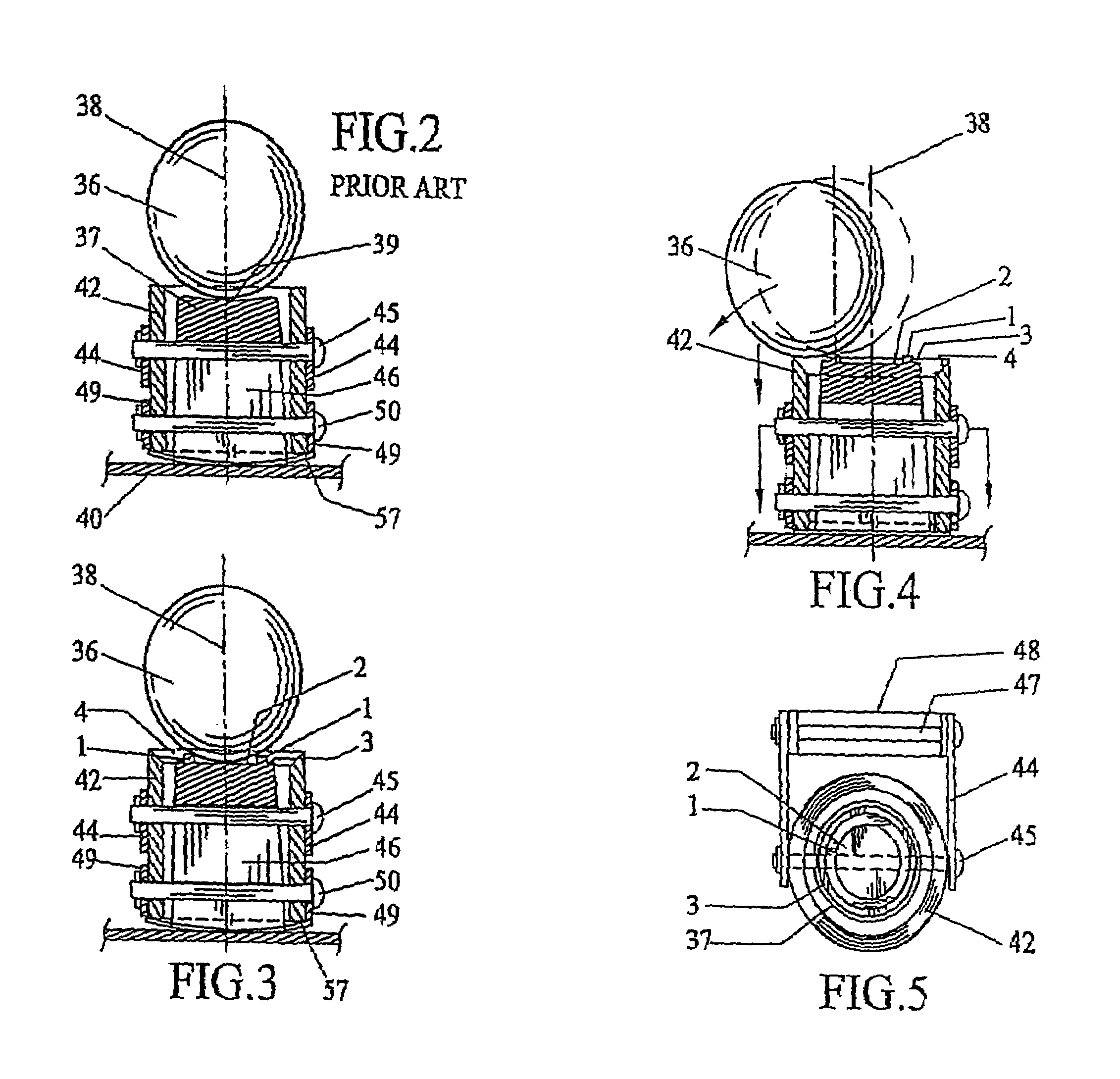
[0065]Referring to FIG. 1, an automatic shock actuated valve of the prior art is illustrated. This valve is that disclosed in U.S. Pat. No. 4,915,122 issued Apr. 10, 1990 and which valve description is incorporated herein by reference for disclosure of the preferred embodiment of the instant invention. The prior art reference includes as co-inventors the two inventors of this instant disclosure. While this...


PUM


Abstract

A shock responsive fluid valve assembly capable of automatically closing a fluid valve in response to earthquake forces or other shock forces of a predetermined magnitude. The shock responsive valve assembly has a flow control mechanism having a cradle that holds a movable ball in a recess at a point perpendicular in relation to a horizontal base plate, where the ball can be rotated 360° in any direction during seismic actions or other shock forces and rolls out of its recess at a predetermined force such that it ricochets off a housing cover covering the cradle and pushes a trip fork mechanism having elongated walls to provide additional leverage when the force strikes the trip fork mechanism that is mounted on a pivoting mechanism, thereby releasing a swing arm which has a disc on the end that functions as a plug for the hole in the valve body to interrupt gas or fluid flow therein. The improvement comprises a novel reset valve mechanism so that a respective reset valve mechanism is located on both sides of the valve body. In this way, regardless of how the valve mechanism is installed, at least one reset valve mechanism will be on the side of the valve body away from the structure wall and will be easily accessible to reset the valve after it is tripped.

Description

[0001]This application is a continuation-in-part of application Ser. No. 10 / 641,312 filed on Aug. 13, 2003, now U.S. Pat. No. 6,814,100, which is a continuation-in-part of patent application Ser. No. 10 / 367,425 filed on Feb. 14, 2003, now U.S. Pat. No. 6,789,560, which is a continuation-in-part of patent application Ser. No. 10 / 300,973 filed on Nov. 20, 2002, now pending, which is a continuation-in-part of patent application Ser. No. 10 / 160,981 filed on May 30, 2002, now U.S. Pat. No. 6,527,004 issued Mar. 4, 2003, which application is a continuation-in-part of application Ser. No. 10 / 041,102 filed on Dec. 28, 2001, now U.S. Pat. No. 6,502,599 issued Jan. 7, 2003, which patent is a continuation-in-part of application Ser. No. 09 / 668,003 filed on Sep. 21, 2000, now U.S. Pat. No. 6,394,122 issued May 28, 2002.BACKGROUND OF THE INVENTION[0002]1. Field of the Invention[0003]This invention relates to valves and valve devices for automatically closing a valve to stop the flow of a fluid i...

Claims


Application Information

Patent Timeline
IPC IPC(8): F16K17/36F16K37/00G05G17/00
CPCF16K17/363F16K37/0033F16K37/0041Y10T137/0753Y10T137/0777
Inventor SIBLEY, RICHARD D.
Owner PACIFIC SEISMIC PRODS
Why Eureka
Try Eureka