Solenoid valve

a solenoid valve and valve body technology, applied in the direction of valve details, valve arrangement, valve seals, etc., can solve the problems of complication of construction, gap between these parts, and increase in the number of parts

Inactive Publication Date: 2005-11-29
EAGLE INDS
View PDF10 Cites 10 Cited by
  • Summary
  • Abstract
  • Description
  • Claims
  • Application Information

AI Technical Summary

Benefits of technology

[0039]According to this structure, the seal member seals each of the inner circumferential surface of the case member and the substantially flat surface portion of the plate, so that the entry of the water (contaminants), which causes a poor insulation of the coil and the short-circuiting, from the outside can be prevented. Moreover, the sealing of the substantially flat surface portion of the plate and one surface of the collar enables the leakage of the fluid from an inside to be prevented. Therefore, one seal member enables the entry of water (contaminants), which causes a poor insulation of the coil and the short-circuiting thereof, from the outside, and the leakage of the fluid from an inside to be prevented.
[0048]According to this structure, a radial inward movement is restricted with the position restricting portion, so that the sealing performance of the second seal surface even with respect to a variation of an axial size is maintained. Moreover, when a load is imparted in the axial direction, a sufficient sealing performance is delivered by either one of the seal portion flexibly deformable toward the inner circumferential surface of the case member and the contact portion.
[0051]Owing to this structure, one seal member, i.e. even such a simple seal member as the O-ring can prevent the entry of the water (contaminants), which causes a poor insulation of the coil and the short-circuiting, from the outside, and the leakage of a fluid from inside.
[0061]This can prevent the plate type member from being plastically deformed.

Problems solved by technology

The portion of the center post 202 and that of a valve sleeve 202c at which these two parts are fixed to each other by case-caulking are liable to cause deformation, which results in a gap between these parts.
However, in the above-described conventional art, the following problems occurred.
Although a sufficient sealing performance is thus displayed owing to the use of the two O-rings, an increase in the number of parts and the complication of the construction were invited.

Method used


Image

  • Solenoid valve
  • Solenoid valve
  • Solenoid valve

Examples


first embodiment

(First Embodiment)

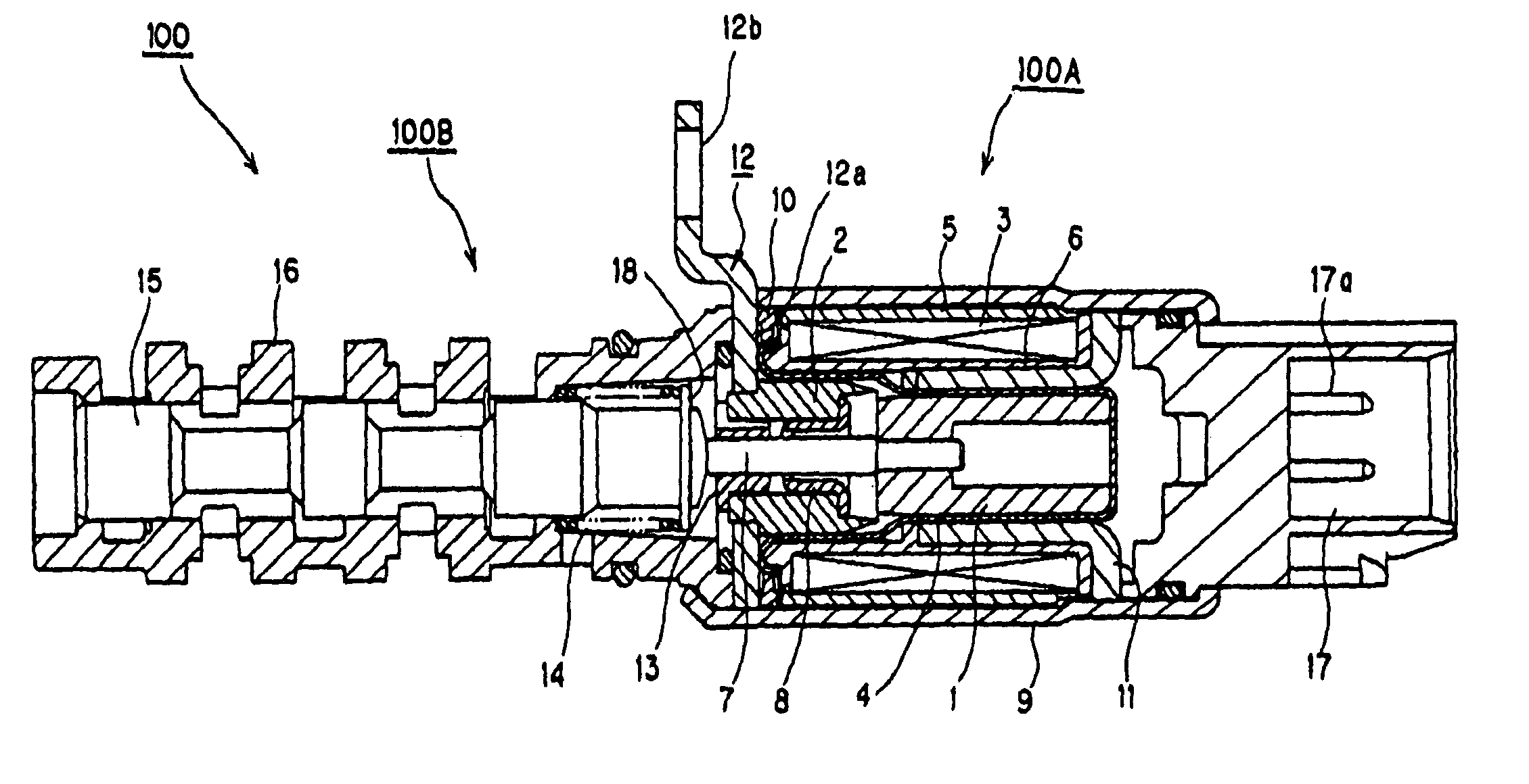
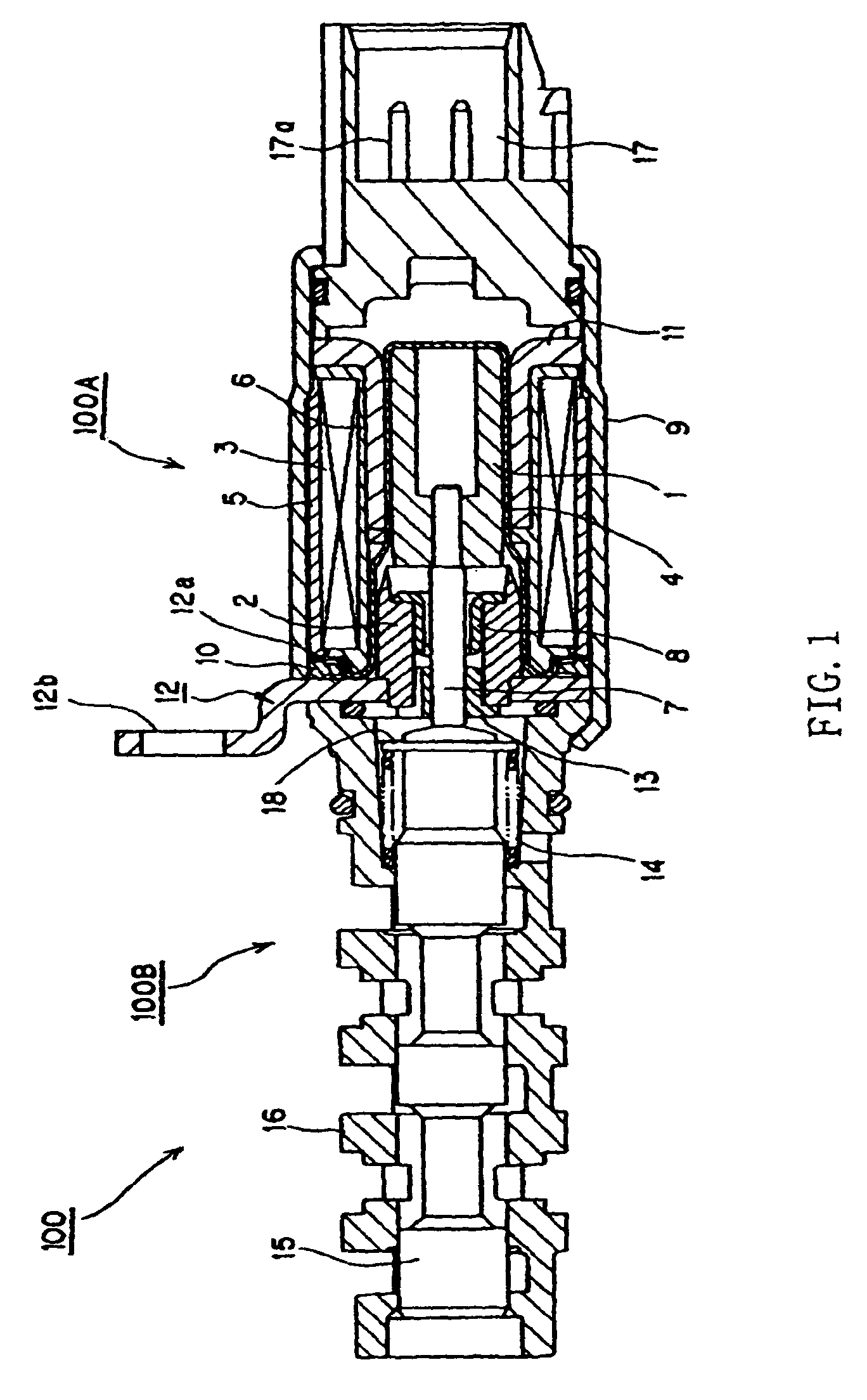
[0070]A first embodiment of the solenoid valve according to the present invention will now be described referring to FIG. 1 and FIG. 2.

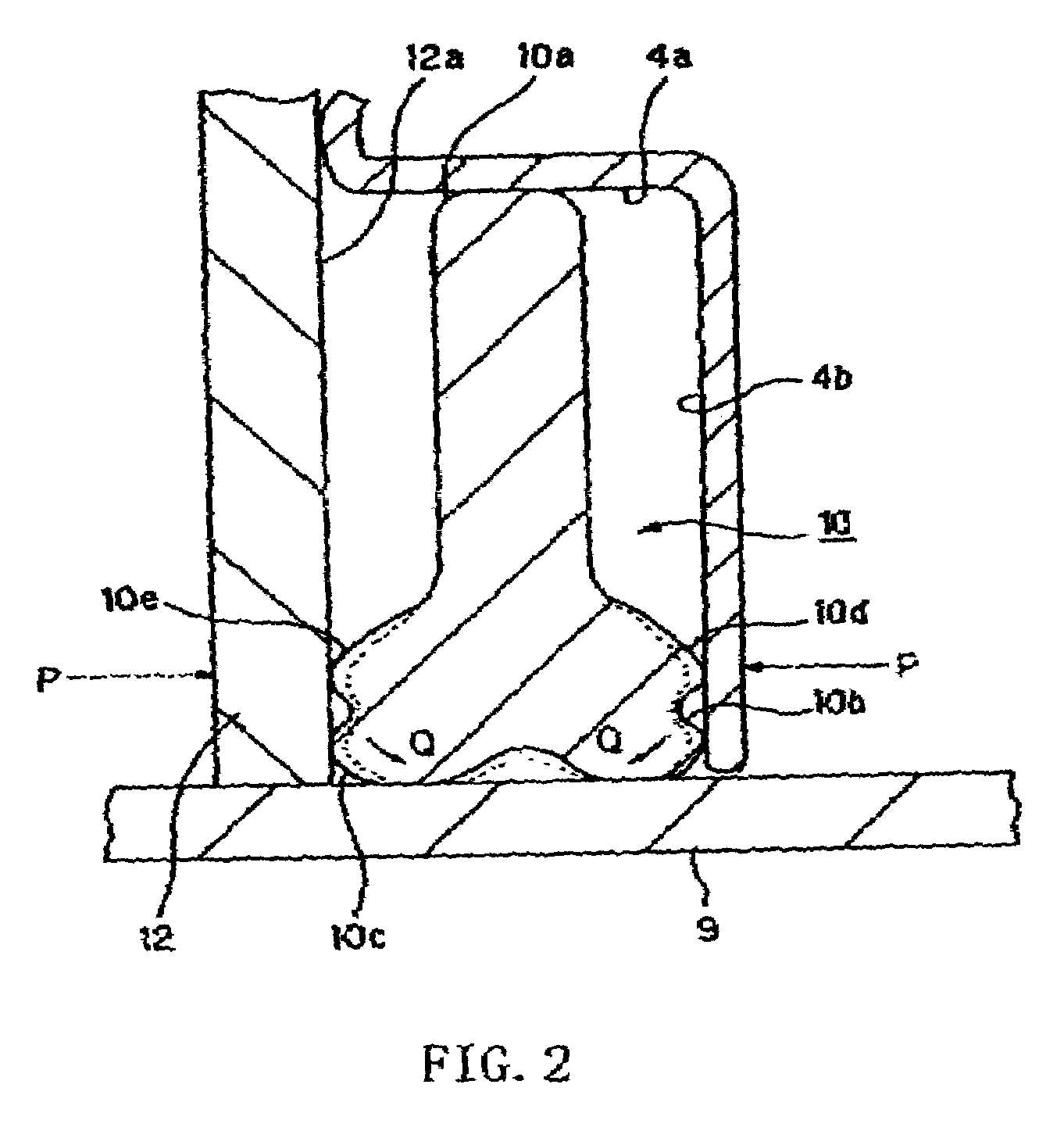
[0071]FIG. 1 is a schematic construction diagram in section of the first embodiment of the solenoid valve according to the present invention, and FIG. 2 is a schematic construction diagram in section of a seal member in an installed state in the first mode of embodiment of the present invention.

[0072]A solenoid valve 100 includes a solenoid portion 100A and a valve portion 100B.

[0073]Here, the valve portion 100B in the illustrated embodiment is made of a spool valve. That is, the valve portion 100B is formed with a spool 15 provided in the interior of a valve sleeve 16 so that the spool 15 can be reciprocated therein, the area of an opening of the valve formed in the valve sleeve 16 varies in accordance with a stroke of the spool 15. Therefore, the controlling of a quantity of stroke of the spool 15 by the solenoid enables an inflow...

second embodiment

(Second Embodiment)

[0113]FIG. 4 shows a second embodiment. In the first embodiment, a case where an annular space is formed in a substantially cylindrical shape with a substantially rectangular cross section and it receives a seal member of a special shape, which can deal with variations of the axial dimensions and shape, was described. In the second embodiment, a case where an annular space is formed to a substantially triangular cross sectional shape with a three-surface sealing in which each surface is sealed by O-rings will be described.

[0114]The other construction and function are identical with those of the first embodiment, so that a description of the same parts will be omitted.

[0115]FIG. 4 is a schematic construction diagram in section of the solenoid valve according to a second embodiment of the present invention. A seal portion shown by an arrow P in the drawing is shown on an enlarged scale (P) in the drawing.

[0116]In the embodiment of the present invention, a collar at ...

third embodiment

(Third Embodiment)

[0124]The solenoid valve according to the present invention of a third embodiment will now be described referring to FIG. 5. Incidentally, in this embodiment the construction except the construction of a seal member and a collar of a sleeve 4 is identical with the first embodiment. Therefore, they only will be described in detail, and a description of the other construction will be omitted.

[0125]FIG. 5 is a schematic construction diagram in section of the seal member in an installed state according to the third embodiment of the present invention.

[0126]In this embodiment, a substantially flat surface portion 4′b of a collar of a sleeve 4 is made elastically deformable. Namely, a substantially flat surface portion 4′b is formed as a flexible leaf spring in which a bent portion 4′d between a cylindrical portion 4′a and substantially flat surface portion 4′b works as a base point where a power is received.

[0127]When a seal member 40 is installed in such a structure, t...


PUM


Abstract

A substantially cylindrical annular space is formed by an outer circumferential surface of a cylindrical portion and a substantially flat surface portion of a substantially bottomed cylindrical sleeve, an inner circumferential surface of a case member, and a substantially flat surface portion of a bracket plate, a seal member being provided in this annular space. Thus, the simplification of the construction, and the miniaturization and the reduction of the weight is realized while a sealing performance between the inside and outside of the main body is maintained.

Description

[0001]This is a nationalization of PCT / JP01 / 09072, filed Oct. 16, 2001 and published in Japanese.TECHNICAL FIELD[0002]This invention relates to a solenoid valve suitably used for controlling, etc., pressures of various kinds of fluids.BACKGROUND ART[0003]The conventional art solenoid valves of this kind include, for example, a solenoid valve shown in FIG. 7. FIG. 7 is a schematic construction diagram in section of the conventional art solenoid valve.[0004]The solenoid valve 200 includes a solenoid portion 200A, and a valve portion 200B.[0005]Here, in the illustrated example, the valve portion 200B represents a spool valve type capable of controlling an inflow rate and an outflow rate of a fluid by varying a cross-sectional area of an opening of the valve in accordance with a stroke of a spool.[0006]The solenoid portion 200A is generally provided with a substantially cylindrical coil 203 adapted to generate a magnetic field when it is energized, a plunger 201 magnetically attracted t...

Claims


Application Information

Patent Timeline
Patent Type & Authority Patents(United States)
IPC IPC(8): F16J15/02F16K31/06
CPCF16J15/024F16K31/0603F16K31/0613F16K31/0668
Inventor HIRATA, ICHIROUEMURA, NORIOKASAGI, YOSHINARIYAMAGUCHI, TADASHI
Owner EAGLE INDS
Why Eureka
Try Eureka