Mounting structure and mounting method for vehicle interior parts
a technology for mounting structures and interior parts, which is applied in the direction of container/bottle construction, rigid containers, lightening support devices, etc., can solve the problems of poor assembling performance of assist grips, laborious work, and laborious work, and achieve the effect of high mounting strength
- Summary
- Abstract
- Description
- Claims
- Application Information
AI Technical Summary
Benefits of technology
Problems solved by technology
Method used
Image

Examples
embodiment 1
(Embodiment 1)
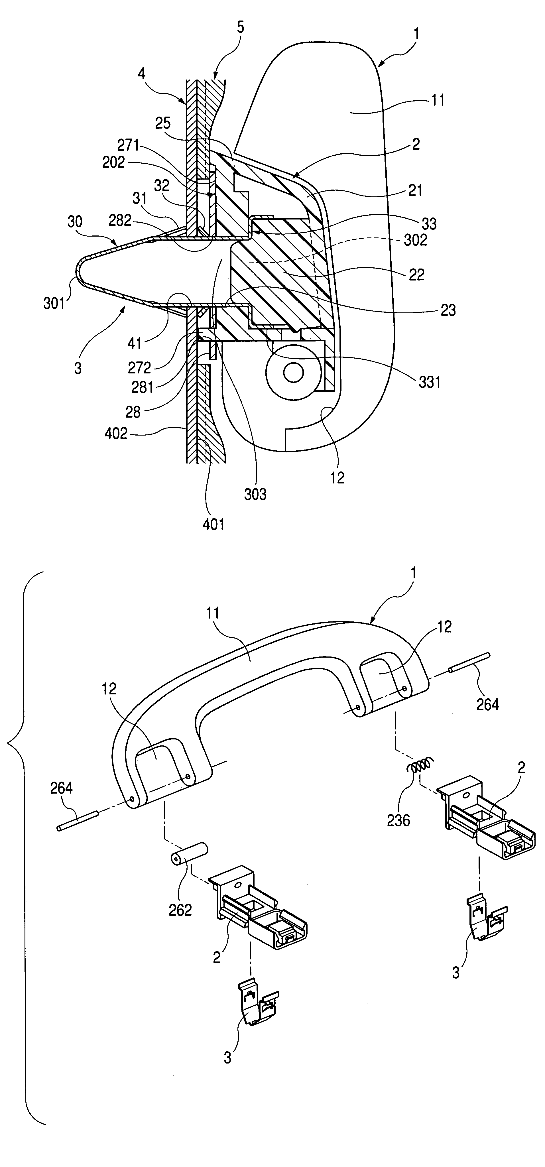
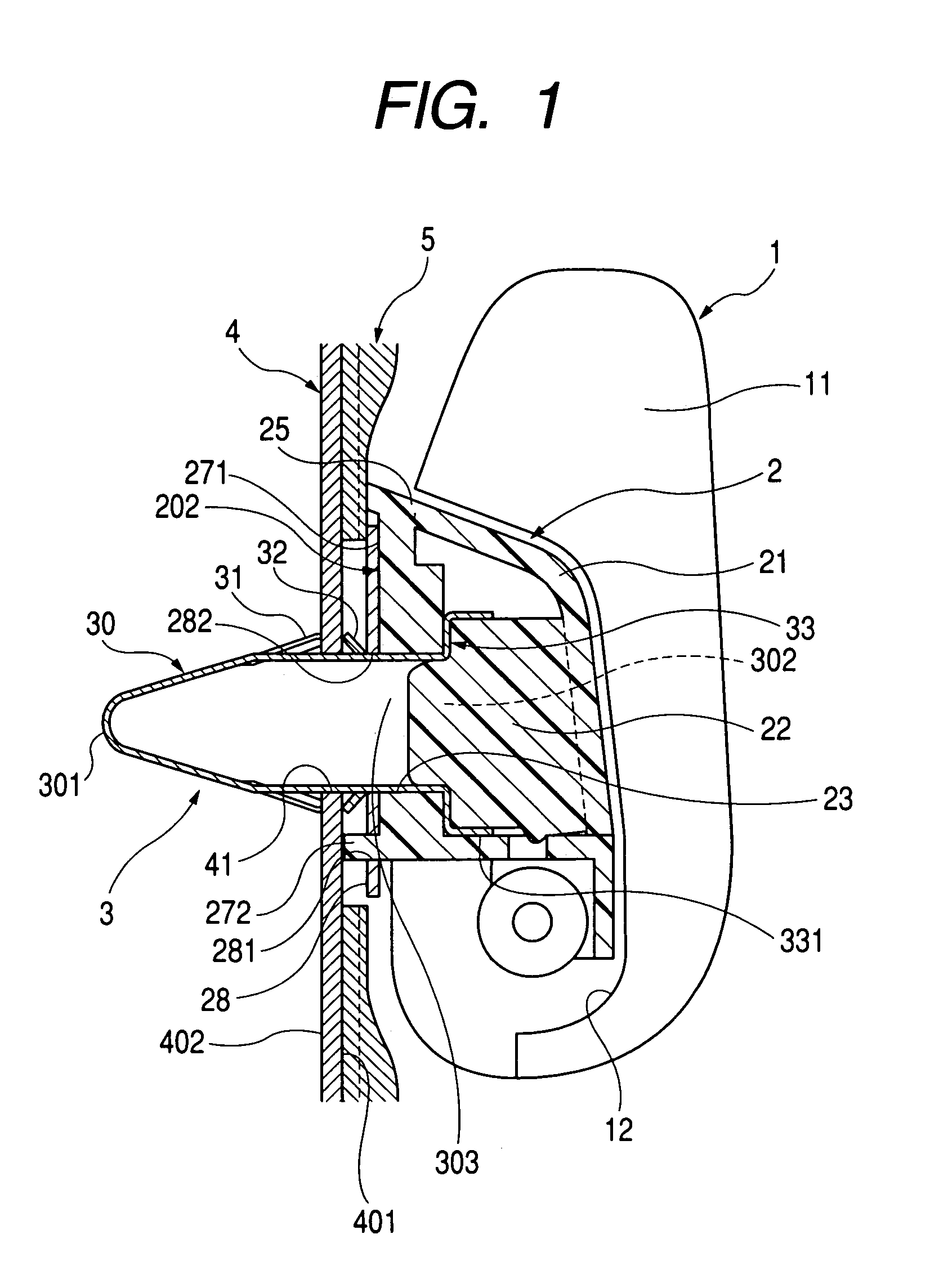
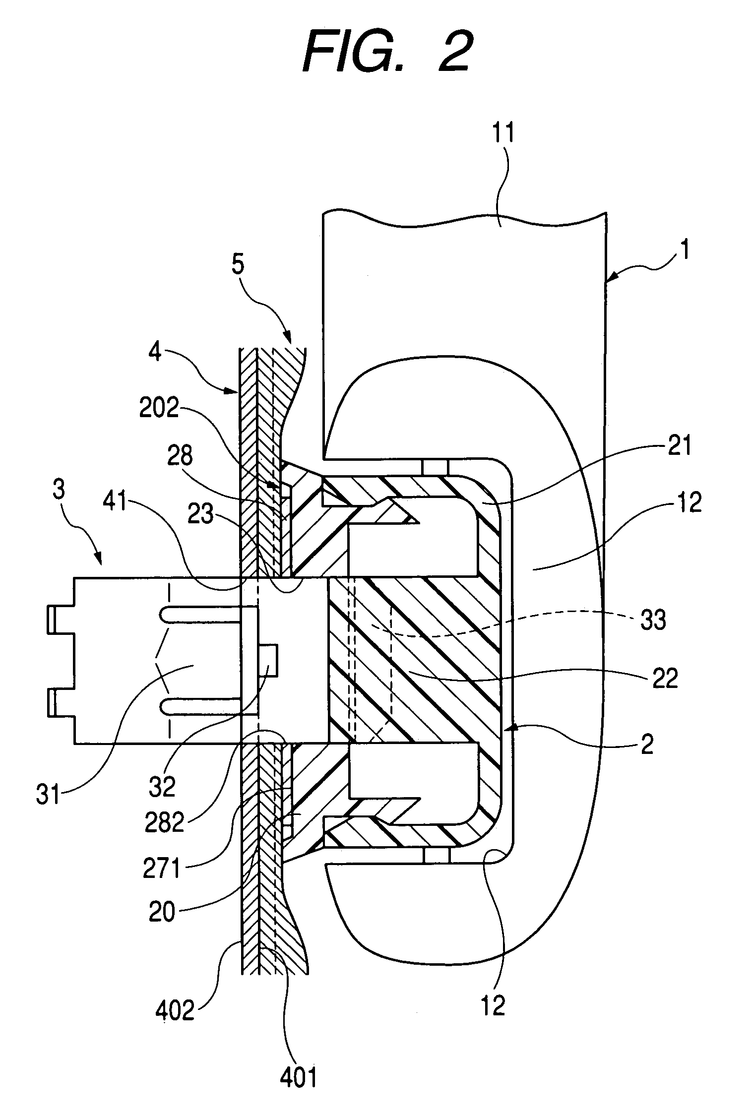
[0177]As shown in FIG. 1 and FIG. 2, in a mounting structure of a vehicle interior part 1 in Embodiment 1, the vehicle interior part 1 is mounted to a body panel 4 via a clip 3.
[0178]The clip 3 includes a pair of left and right leg portions 30, which are connected only at the distal end 301 thereof. Each of the pair of left and right leg portions 30 includes a first locking pawl 31, which engages the back surface 402 of the body panel 4 when being inserted into a panel hole 41 (a hole for inserting the clip 3) formed on the body panel 4, a second locking pawl 32, which engages the front surface 401 of the body panel 4, and an engaging portion 33, which engages the peripheral edge of a clip insertion hole 23 formed on the vehicle interior part 1.
[0179]In the mounting structure described above, the clip 3 is engaged with the vehicle interior part 1 by engaging the engaging portion 33 of the clip 3 with the peripheral edge of the clip insertion hole 23 of the vehicle inte...
embodiment 2
(Embodiment 2)
[0228]FIG. 13 shows an example in which the body contact portion 272 on the assist grip 1 in Embodiment 1 is provided not on the attachment part 2, but on the reinforcing plate 28 to form a body contact portion 283.
[0229]In other words, the body contact portion 283 is formed by bending the reinforcing plate 28. The reinforcing plate 28 of Embodiment 2 does not have the attachment hole 281, and thus punching process is not necessary as in the case of the reinforcing plate 28 of Embodiment 1. The metal plate 28 is located with respect to the attachment part 2 by inserting the clip 3 into the clip insertion hole 23 of the attachment part 2, and into the through hole 282. Other constructions are the same as Embodiment 1.
[0230]In Embodiment 2 as well, the attachment part 2 of the assist grip 1 is mounted to the body panel 4 and the interior panel 5 by bringing the opposing surface 202 into abutment with the interior panel 5 and bringing the body contact portion 283 of the r...
embodiment 3
(Embodiment 3)
[0233]This embodiment is an example of the assist grip 1 shown in Embodiment 2, in which the clip 3 is not provided with the second locking pawl 32, and the first locking pawl 31 constitutes the locking device 34 that engages the portion of the body panel 4 in the vicinity of the panel hole 41 as shown in FIG. 14 and FIG. 15.
[0234]In the mounting structure of Embodiment 3, the body panel 4, the interior panel 5, and the base portion 20 of the attachment part 2 are clamped between the locking device 34 and the engaging portion 33 by engagement between the locking device 34 of the clip 3 and the portion of the body panel 4 in the vicinity of the panel hole 41 and engagement between the engaging portion 33 of the clip 3 and the peripheral edge of the clip insertion hole 23 on the attachment part 2 of the assist grip 1.
[0235]According to Embodiment 3, the shape of the pressure plug 22 provided on the cap 21 is inventive. In other words, as shown in FIG. 16, the pressure pl...
PUM
 Abstract
Description
Claims
Application Information
 - R&D
- Intellectual Property
- Life Sciences
- Materials
- Tech Scout
- Unparalleled Data Quality
- Higher Quality Content
- 60% Fewer Hallucinations
Browse by: Latest US Patents, China's latest patents, Technical Efficacy Thesaurus, Application Domain, Technology Topic, Popular Technical Reports.
© 2025 PatSnap. All rights reserved.Legal|Privacy policy|Modern Slavery Act Transparency Statement|Sitemap|About US| Contact US: help@patsnap.com