Electric parking brake system

a technology of electric parking brake and brake plate, which is applied in the direction of brake system, brake components, instruments, etc., can solve the problems of increasing the cost of the electric parking brake system, affecting the stability of the braking system, and reducing the reliability and stability of the braking performance, so as to achieve high-quality braking performance and early detection

Inactive Publication Date: 2005-11-29
ASMO CO LTD
View PDF5 Cites 20 Cited by
  • Summary
  • Abstract
  • Description
  • Claims
  • Application Information

AI Technical Summary

Benefits of technology

[0010]It is a first object of the present invention to provide an electric parking brake system featuring highly stable braking perfor...

Problems solved by technology

In an emergency operation mode, specifically, in a parking-brake applying operation where one of the electric parking brakes is not functioning, reliability and stability of the braking performance is degraded.
This complicates the structure and increases the cost of the electric parking brake system.
Further, the electric parking brake arranged at the location may become wet.
Accordingly, a failure is more likely to occur in the electronic control unit...

Method used


Image

  • Electric parking brake system
  • Electric parking brake system
  • Electric parking brake system

Examples


first embodiment

[0024]The following describes the present invention, with reference to FIGS. 1 to 4.

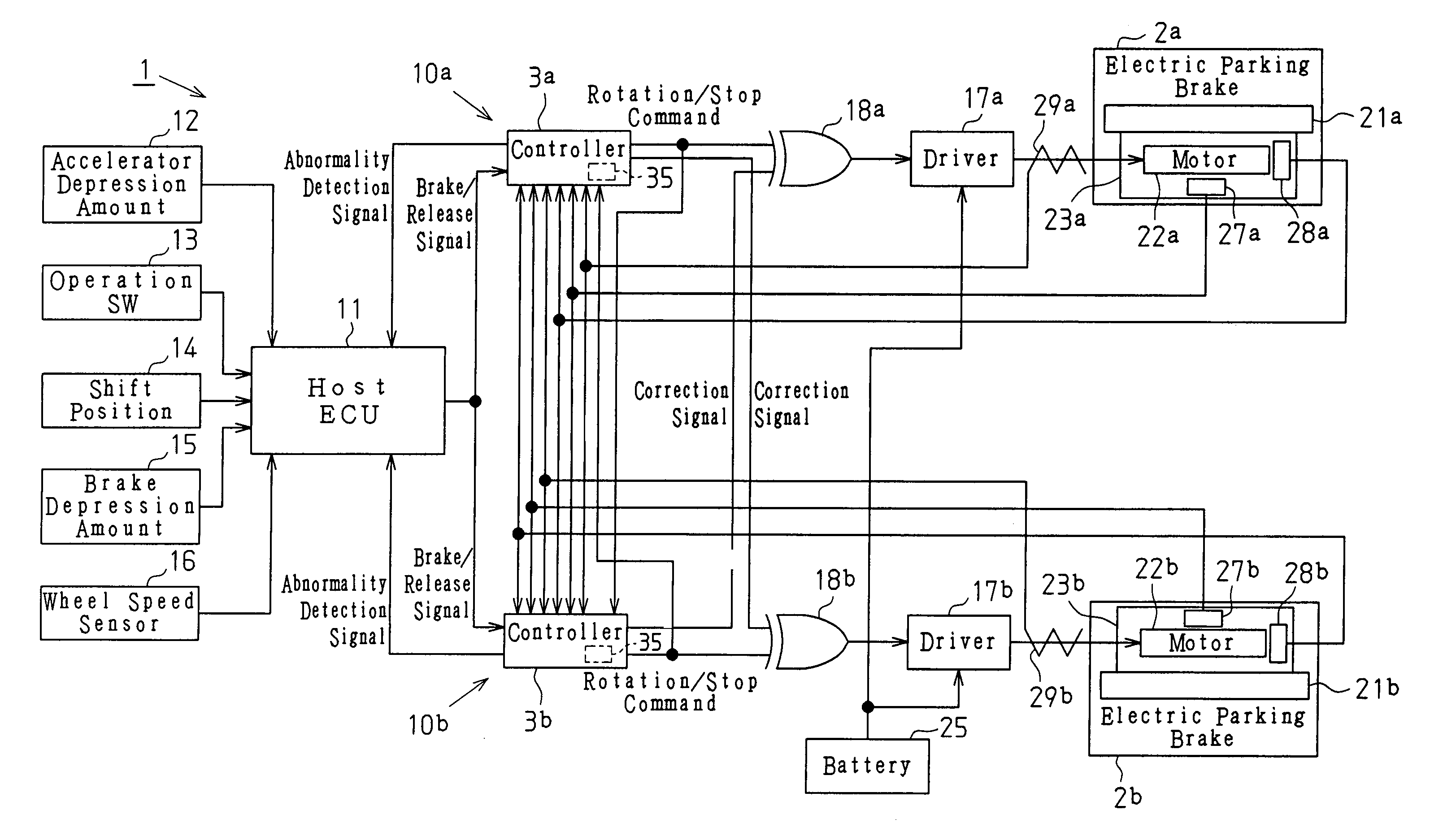
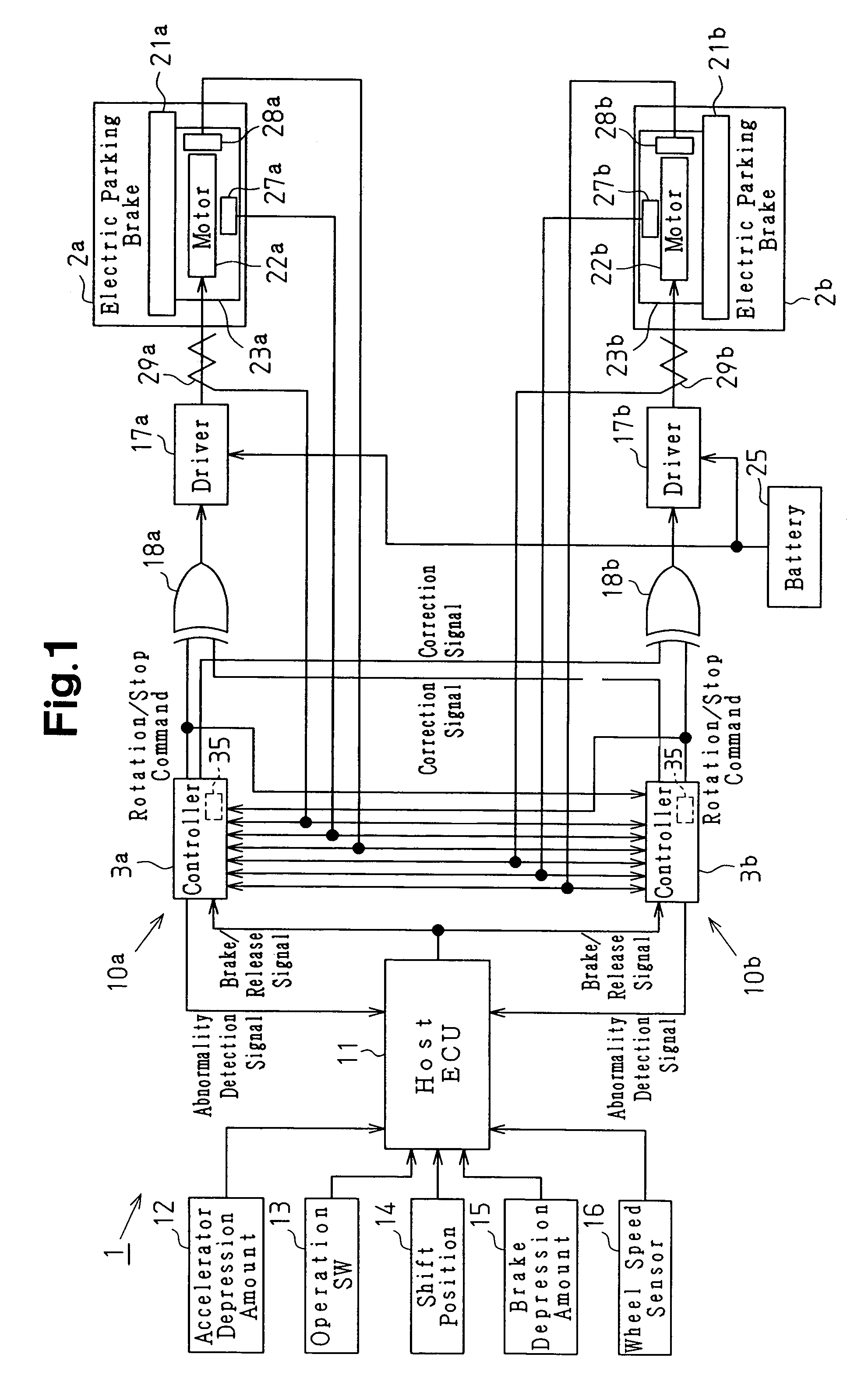
[0025]As shown in FIG. 1, an electric parking brake system 1 includes a first brake system section 10a, a second brake system section 10b, and a host ECU (electronic control unit) 11. The host ECU 11 outputs a brake command signal to each of the first brake system section 10a and the second brake system section 10b. The first brake system section 10a includes an electric parking brake 2a and a controller 3a. The controller 3a outputs a drive command for controlling the operation of the electric parking brake 2a. The second brake system section 10b includes an electric parking brake 2b and a controller 3b. The controller 3b outputs a drive command for controlling the operation of the electric parking brake 2b. The host ECU 11 controls parking braking of the vehicle by outputting a brake command signal (a brake apply signal or a brake release signal) to each of the controllers 3a and 3b included in the...

second embodiment

[0075]The following describes the present invention, with reference to FIGS. 5 to 9 while incorporating FIG. 1. The present embodiment differs from the embodiment illustrated in FIGS. 1 to 4 in that each of the controllers 3a and 3b includes a memory 35 (see FIG. 1). The components in the present embodiment that are the same as the components in the embodiment illustrated in FIGS. 1 to 4 are given the same reference numerals as those components, and are not described here. In the present embodiment, because the first brake system section 10a and the second brake system section 10b have the same structure, the following description is focused on the structure of the first brake system section 10a.

[0076]As shown in FIG. 5, the memory 35 stores a control table 36. The control table 36 defines the correspondence between the brake command signal, the elapsed time, the signals input from the sensors 27a, 28a, and 29a, and the location where a failure has occurred (and its cause).

[0077]In...


PUM


Abstract

A sensor included in each brake system section detects the operation state of an electric parking brake in another brake system section. Based on the detected operation state, the sensor assumes the drive command that is to be output from a controller of the other brake system section to a controller of its own brake system section. The controller of one brake system receives an input of a drive command that is output from the controller of the other brake system. The controller of one brake system compares the assumed drive command (internal value) with the input drive command (input value). When the internal value and the input value do not match, the controller determines that an abnormality has occurred in the other brake system section.

Description

BACKGROUND OF THE INVENTION[0001]The present invention relates to an electric parking brake system.[0002]An electric parking brake system including an electric parking brake and a controller is conventionally known. The electric parking brake is driven by a motor to apply braking force to wheels.[0003]As one example, Japanese National Phase Laid-Open Patent Publication No. 2001-523616 discloses an electric parking brake system including a brake actuator, an electronic control unit that includes a plurality of controllers for separately processing input signals to convert the signals into the corresponding output signals, and a plurality of electric parking brakes that are actuated in accordance with the output signals. The electric parking brake system further comprises a voter that is connected downstream of the controllers and to give decisions based on the majority vote.[0004]According to the above structure, even when an electric failure occurs in a circuit including one of the ...

Claims


Application Information

Patent Timeline
IPC IPC(8): B60T13/66B60T13/74B60T17/18F16D65/14G06F17/00
CPCB60T13/741F16D65/18F16D2066/003F16D2066/005F16D2066/006F16D2121/24
Inventor SUZUKI, HIDETOSHIINA, EIJI
Owner ASMO CO LTD
Why Eureka
Try Eureka