
Ink supply system, ink jet printing apparatus, ink container, ink refilling container and ink jet cartridge

a technology ink jet printing apparatus, which is applied in the field of ink supply system, ink container, ink refilling container and ink jet cartridge, can solve the problems of affecting the quality of printed images, so as to achieve the effect of easily and smoothly supplying a predetermined volume of ink

Inactive Publication Date: 2005-11-29
CANON KK
View PDF27 Cites 98 Cited by
  • Summary
  • Abstract
  • Description
  • Claims
  • Application Information

AI Technical Summary

Benefits of technology

[0021]It is an object of the present invention to provide an ink supply system, an ink jet printing apparatus, an ink container, an ink refilling container and an ink jet cartridge which, when intermittently supplying ink through a disconnectable connect portion, can supply a predetermined volume of ink easily and smoothly.
[0022]Another object of the present invention is to provide an ink supply system, an ink jet printing apparatus, an ink container, an ink refilling container and an ink jet cartridge which can quickly and smoothly discharge a gas which enters into the ink supply system as ink is supplied intermittently from the ink container into the ink refilling container through disconnectable connect portions, without complicating their structure and mechanism.
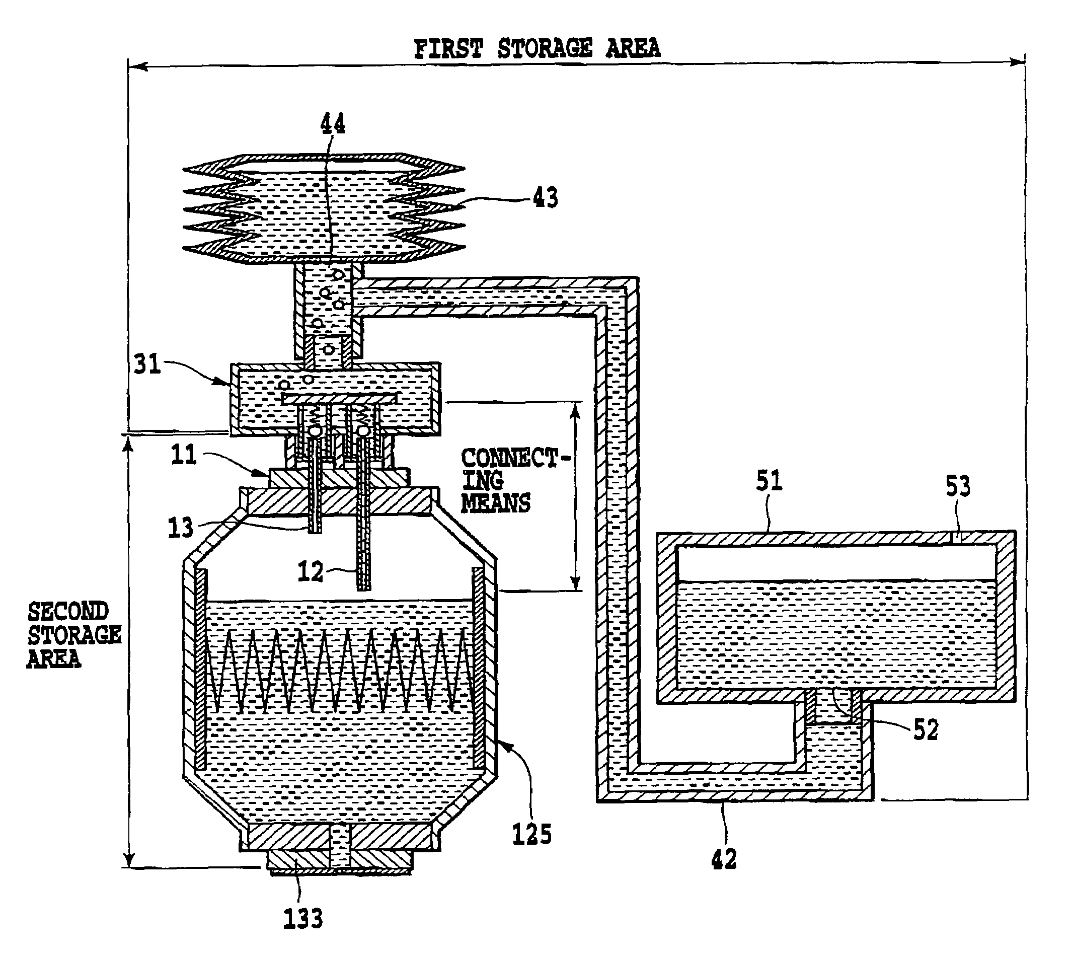
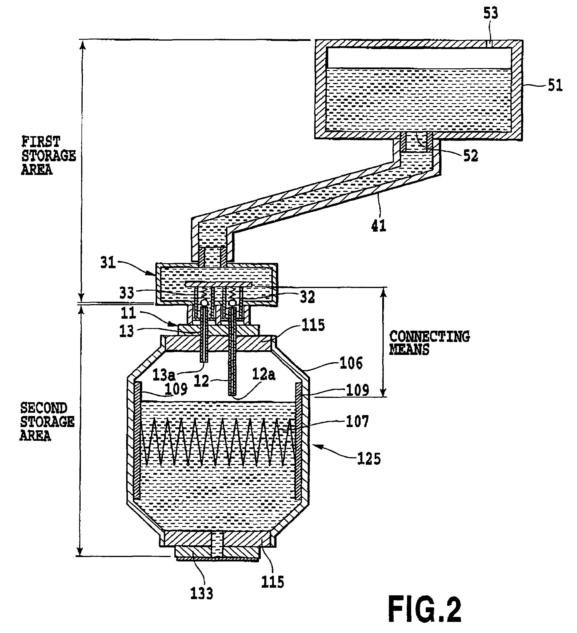
[0043]In a system that intermittently supplies ink from the first ink tank (ink refilling container) to the second ink tank (ink container) through a disconnectable connecting portion, the construction of this invention can efficiently discharge gas from the second ink tank during the ink supply operation. Further, the gas in the second ink tank can be discharged out into the first ink tank and since the gas discharged into the first ink tank moves up, it is prevented from returning into the second ink tank. This can be explained by the principle described below.
[0045]According to the present invention, in intermittently supplying ink from a first ink storage area to a second ink storage area through a disconnectable connection means, the present invention enables ink to be supplied efficiently into the second ink storage area while discharging a gas from the second ink storage area. Further, with this invention, the supply of ink accompanied by the discharge of gas can be implemented without using a driving power source such as a pump and no special time is needed for discharging the gas.

Problems solved by technology

With this method, however, mounting the large ink tank on the carriage increases the weight of the carriage, making it difficult to stably drive the carriage in the main scan direction at high speed and leading to a possible increase in the size of a carriage drive system.
This method also has a drawback that variations in carriage moving load and ink supply pressure resulting from deformations of the tube as the carriage moves may degrade a quality of a printed image.
After the subtank is supplied and overflowed with ink, the carriage is moved away from the predetermined position to disconnect the joint of the subtank from the joint of the main tank, thus disrupting the ink supply path and the ink recovery path.
Further, since it is necessary to recover the ink overflowing from the subtank, the printing apparatus is likely to become complex in construction and large in size.
The apparatus of the Patent Reference 2 also uses a suction produced by a pump in supplying ink, so its size may become large.
Further, in this apparatus since air is actively introduced into the second ink container on the carriage during printing, when the ink in the second ink container is supplied continuously to the print head in a relatively large volume for printing, the air introduced into the second ink container may be drawn into the print head causing a printing failure.
This puts limitations on their arrangements and sizes.
Further, the air in the second ink container on the carriage expands and contracts due to environmental variations such as ambient temperature and pressure changes causing pressure changes in the second ink container.
Positive pressures as a result of pressure changes may cause ink leakage from nozzles of the print head.
Conversely, excessive negative pressures may result in an improper ink ejection or a failure to eject ink.
This hinders a reduction in the size of the print head.
Increasing the size of the capillary tube member may lead to an increased size of the print head and a more complicated structure.
When a means such as pump to forcibly move a gas out of the second ink container is not used, even if the ink is supplied intermittently from the first ink container to the second ink container, the gas accumulated in the second ink container cannot be removed and will degrade an efficiency of ink refilling into the second ink container.

Method used


Image

  • Ink supply system, ink jet printing apparatus, ink container, ink refilling container and ink jet cartridge
  • Ink supply system, ink jet printing apparatus, ink container, ink refilling container and ink jet cartridge
  • Ink supply system, ink jet printing apparatus, ink container, ink refilling container and ink jet cartridge

Examples


first embodiment

[0079](First Embodiment)

[0080][Outline Construction of Printing Apparatus]

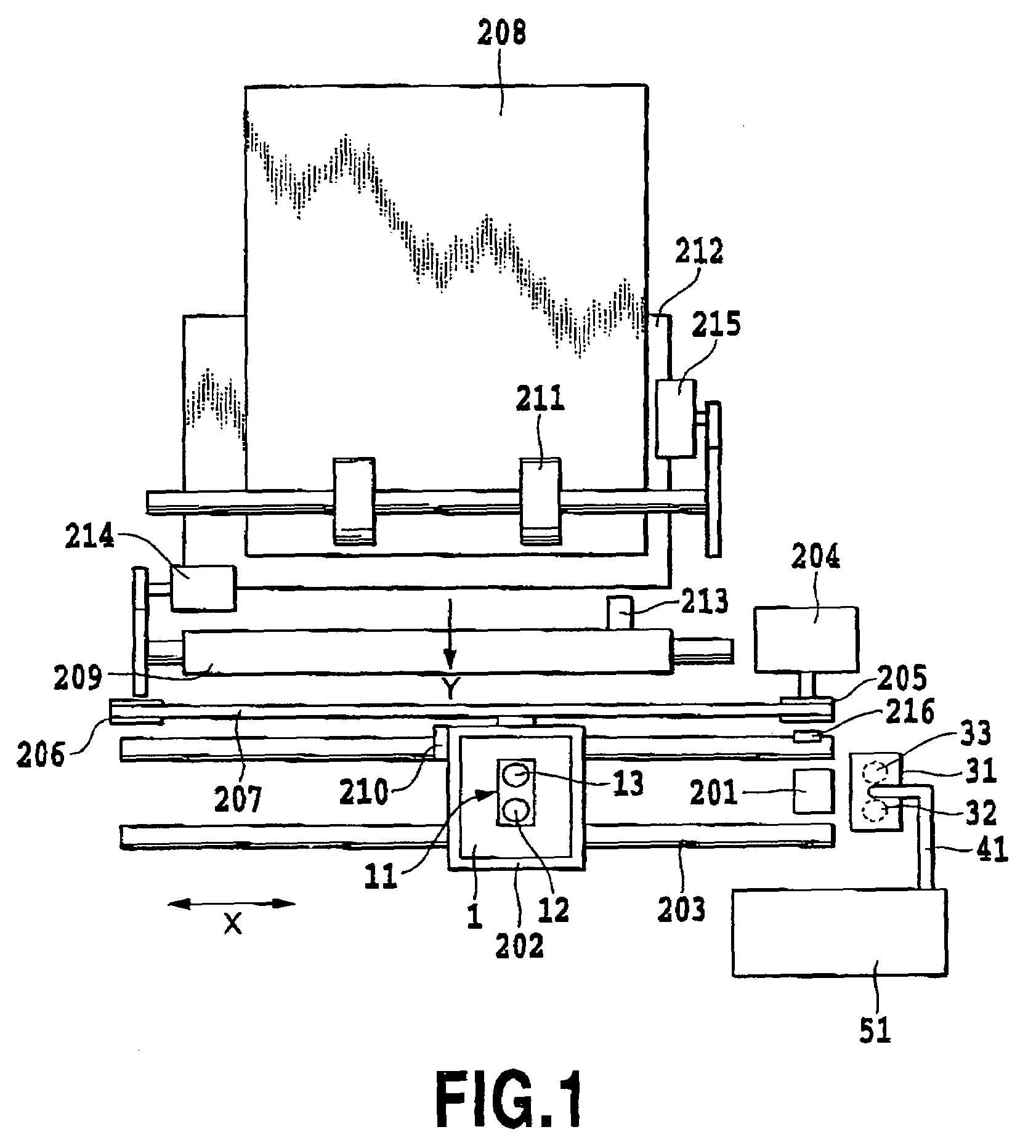
[0081]FIG. 1 is a schematic plan view showing an outline construction of an ink jet printing apparatus as a first embodiment of the present invention.

[0082]In FIG. 1 an ink jet cartridge (hereinafter referred to as a “head unit”) 1 is positioned and replaceably mounted on a carriage 202. The head unit 1 has an ink jet print head, a second ink tank connected to the print head and two tubes 12, 13 communicating with the second ink tank. One of the tubes 12 is called an ink introducing tube because it has a function of mainly introducing ink into the second ink tank. The other tube 13 is called a gas discharge tube as it has a function of mainly discharging air from the second ink tank. However, as described later, the ink introduction and air discharging are each performed by both of these tubes 12, 13. Hence, their names do not mean that they are dedicated to either ink introduction or air discharging function....

second embodiment

[0130](Second Embodiment)

[0131]FIG. 5 illustrates a second embodiment of the present invention. This embodiment represents a case where the first ink tank 51 is not necessarily installed at a position higher than that of the second ink tank 125. In this example too, as shown in FIG. 5, an area from the first ink tank 51 to the ink path 42 to the supply unit 31 may be defined as a first ink storage area, an area from the ink introducing tube 12 and gas discharge tube 13 to the head chip 133 as a second ink storage area, and an area from the ink supply tube 32 and gas extraction tube 33 to the ink introducing tube 12 and gas discharge tube 13 as a connecting means.

[0132]As shown in FIG. 5, even when the first ink tank 51 is not installed at a position higher than the second ink tank 125, a connection between the connector 11 and the supply unit 31, both constituting a connection unit, causes the ink to be supplied from the first ink tank 51 to the second ink tank 125 as in the first e...

third embodiment

[0141](Third Embodiment)

[0142]FIGS. 16 and 17 illustrate a third embodiment of this invention. The first ink container (first ink tank) 51 in this example is partitioned into two chambers, an ink chamber and a valve chamber 68, which are communicated with each other through a communication port 56.

[0143]A deformable, flexible film (sheet member) 52 is provided in one part of the first ink container 51. Between the sheet member 52 and an inner surface of the first ink container 51 is formed a space (ink chamber) to accommodate ink. A space in the first ink container 51 on the outside of the sheet member 52, i.e., a space above the sheet member 52 in FIG. 16, is open to an atmosphere through an open air communication port 55 and set equal to an atmospheric pressure. The first ink container 51, excluding a connect portion for the supply unit 31 provided below and a communication path to the valve chamber 68, essentially forms a hermetically closed space.

[0144]A central portion of the s...


PUM


Abstract

An ink supply system, an ink jet printing apparatus, an ink tank and an ink jet cartridge are provided which, in intermittently supplying ink through a disconnectable connecting portion, can smoothly supply a required volume of ink easily, and can quickly and smoothly discharge a gas which enters into the ink supply system without complicating their structure and mechanism. The first ink tank and the second ink tank are disconnectably connected through the supply unit and the connector. Two communication paths connecting the ink tanks are formed by the tubes. Gas in the second ink tank is discharged through one of the communication paths and at the same time ink in the first ink tank is supplied to the second ink tank through the other communication path.

Description

[0001]This application claims priority from Japanese Patent Application No. 2002-287834 filed Sep. 30, 2002, which is incorporated hereinto by reference.BACKGROUND OF THE INVENTION[0002]1. Field of the Invention[0003]The present invention relates to an ink supply system for supplying ink through a connect portion that can be connected and disconnected, an ink jet printing apparatus, an ink container, an ink refilling container and an ink jet cartridge.[0004]2. Description of the Related Art[0005]Among printing apparatus that print an image on a print medium by applying ink from a print head onto a print medium, there is a serial scan type printing apparatus that applies ink from the print head onto the print medium while moving the print head. As the print head an ink jet print head which can eject ink toward the print medium may be used.[0006]In general, the serial scan type printing apparatus using an ink jet print head print an image on a print medium by repetitively alternating ...

Claims


Application Information

Patent Timeline
Patent Type & Authority Patents(United States)
IPC IPC(8): B41J2/175
CPCB41J2/17509B41J2/175
Inventor KUWABARA, NOBUYUKIISHINAGA, HIROYUKIOHASHI, TETSUYAINOUE, RYOJIOGURA, HIDEKI
Owner CANON KK
Learn More