Flow directing device

Inactive Publication Date: 2005-11-29
RAYTHEON TECH CORP
View PDF18 Cites 105 Cited by
  • Summary
  • Abstract
  • Description
  • Claims
  • Application Information

AI Technical Summary

Benefits of technology

[0020]These and other objects of the present invention are achieved in another aspect by a method of reducing heat load on an airfoil. The method comprises the steps of: providing an airfoil with a proximal end that abuts a wall, a distal end and a medial section between sai

Problems solved by technology

The horseshoe vortex detrimentally affects components near the airfoil.
For example, the horseshoe vortex affects the useful life of the wall.
Unlike the airfoil, the platform lacks any cooling schemes that can offset the augmented heat load.
The horseshoe vortex als

Method used


Image

  • Flow directing device
  • Flow directing device
  • Flow directing device

Examples


Embodiment Construction

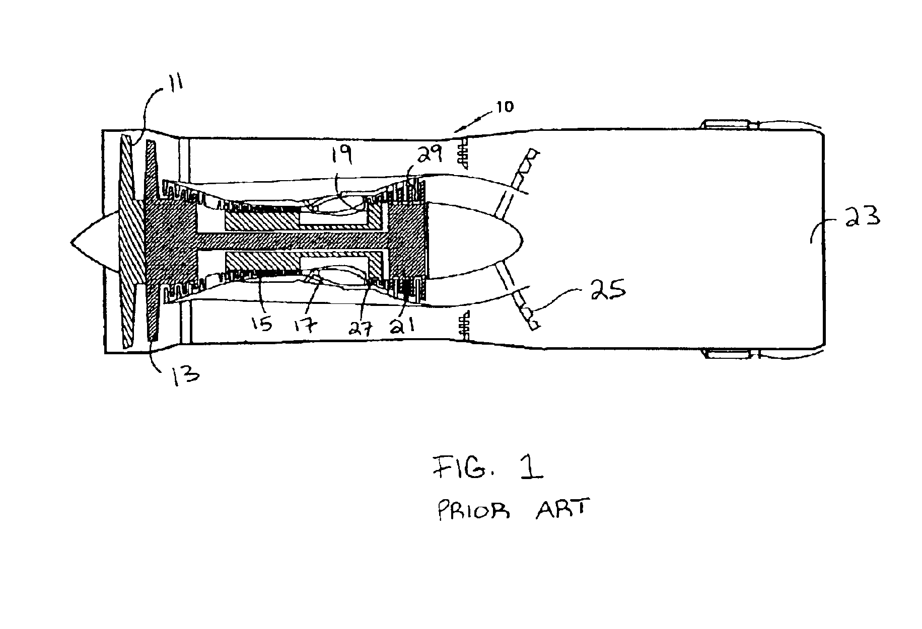
[0029]FIG. 1 displays a gas turbine engine 10. The engine 10 has a fan section 11, compressor section 13, 15, a burner section 17, turbine sections 19, 21 and a nozzle 23. The engine could also include an afterburner 25. The compressor sections 13, 15 and the turbine sections 19, 21 each include alternating arrangements of stator vane stages 27 and rotor stages 29. The stator vane stages 27 guide core gas flow into or out of an adjacent rotor stage 29.

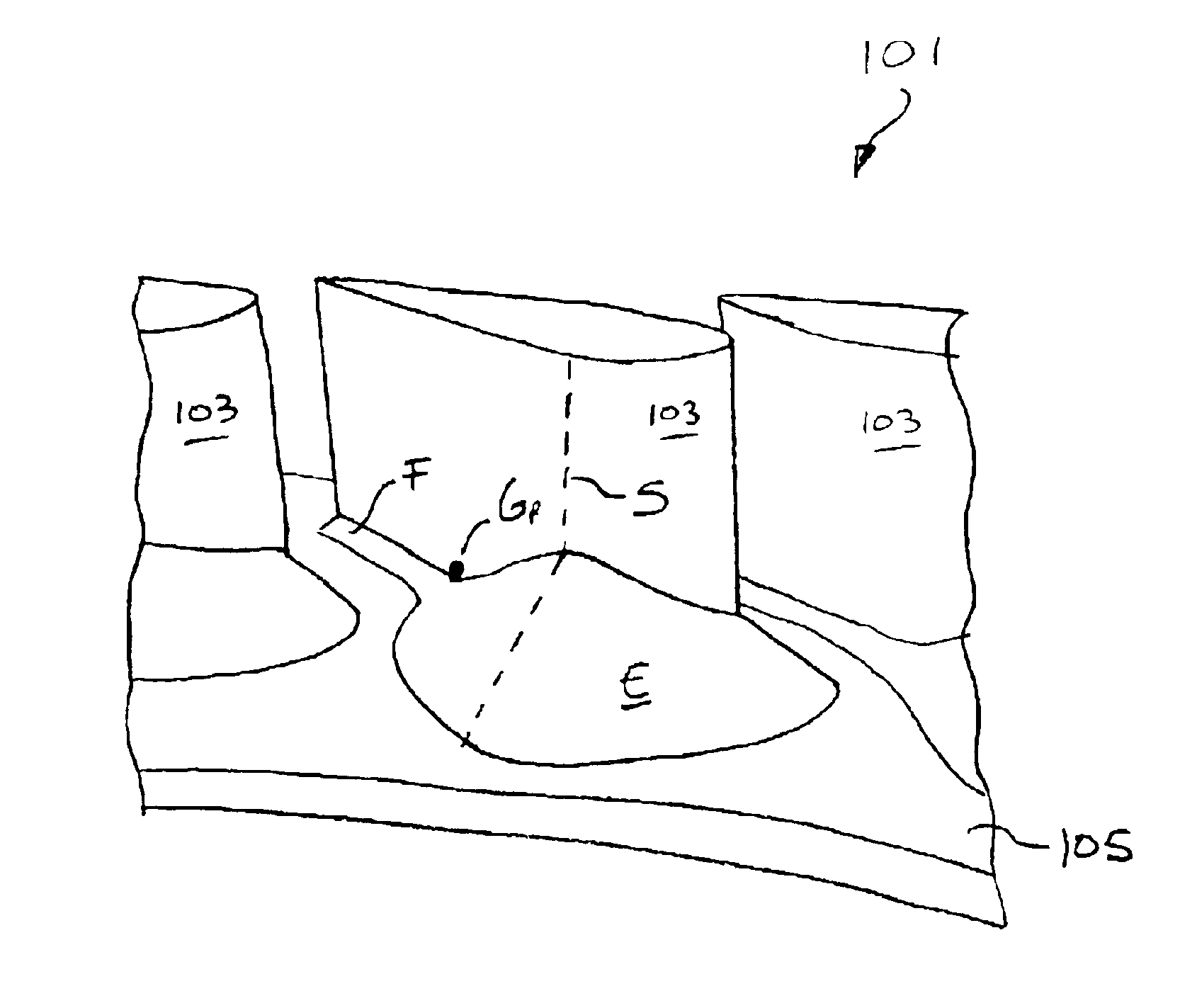
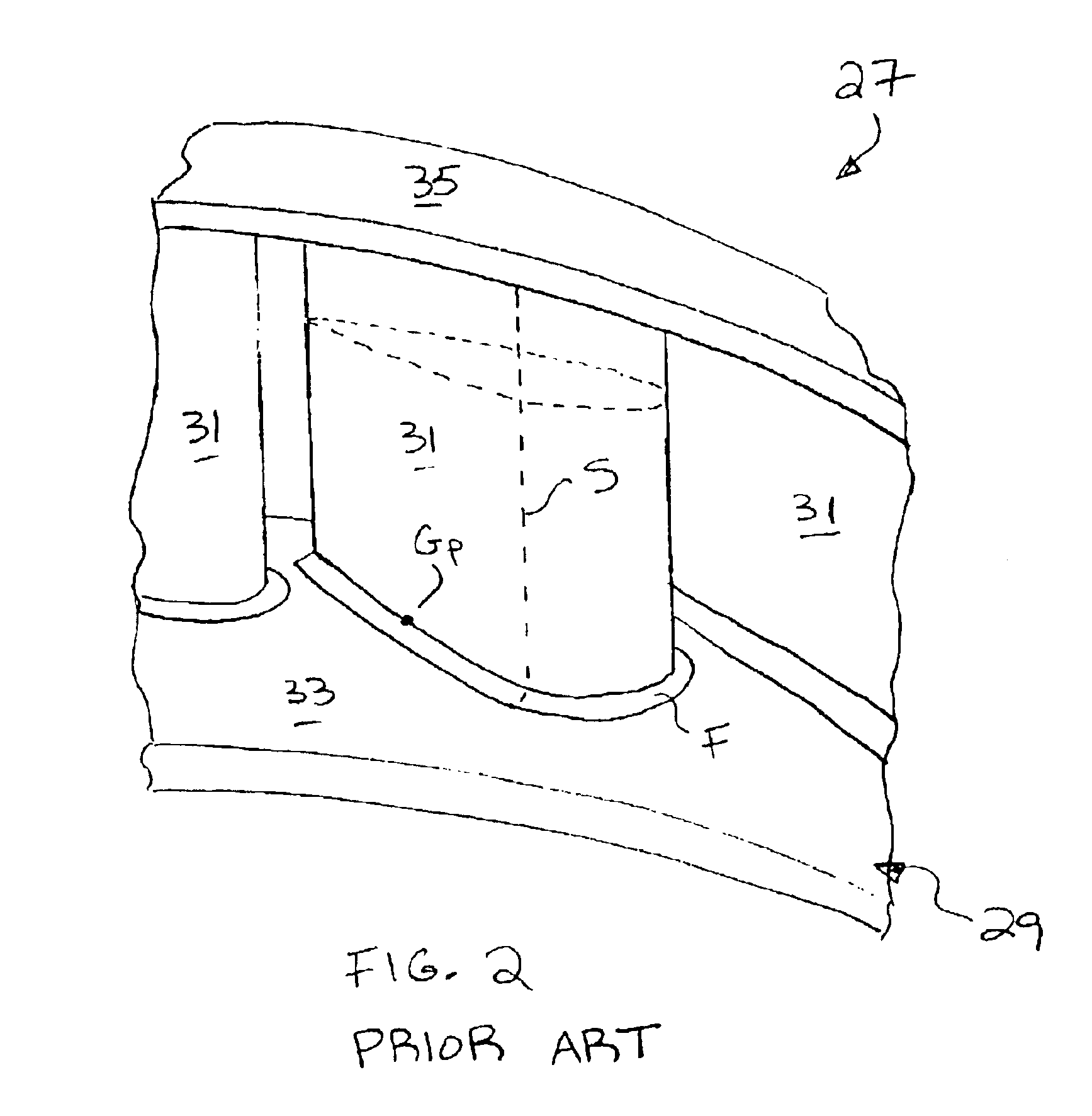
[0030]FIG. 2 displays one of the stator vane stages 27. The stage 27 is segmented into stator vane clusters 29. Each cluster 29 has one or more airfoils 31 extending between an inner platform 33 and an outer platform 35. The platforms 33, 35 define the radial boundaries of the annular core gas path through the engine 10.

[0031]The clusters 29 are typically cast into a rough shape, then machined into a final form. The machining process does not create a perpendicular intersection between the airfoil 31 and the platforms 33, 35. Instead, ...


PUM


Abstract

A flow directing device of a gas turbine engine, comprising: an airfoil having a leading edge, trailing edge, suction side and pressure side; a wall abutting the airfoil; and a fillet between the airfoil and wall. The fillet has an enlarged section at the leading edge, along the suction and pressure sides, and towards the trailing edge. The device could be part of a vane segment. In addition to eliminating a horseshoe vortex, the device also reduces heat load on the airfoil by directing the cooler gas from the proximal end of the airfoil to the hotter gas at the medial section of the airfoil.

Description

FEDERAL RESEARCH STATEMENT[0001]The U.S. Government may have rights in this invention pursuant to Contract No. F33615-98-C-2905 with the United States Air Force.BACKGROUND OF INVENTION[0002]This invention relates to flow directing devices for use in gas turbine engines. Specifically, the present invention relates to an apparatus and a method of reducing heat load on an airfoil exposed to a gas flow.[0003]The major components of a gas turbine engine include (beginning at the upstream end, or inlet) a fan section, one or more compressor sections, a burner section, one or more turbine sections, and a nozzle. The engine may also include an afterburner.[0004]Air enters the engine through the inlet, travels past the fan section, becomes compressed by the compressor sections, mixes with fuel, and combusts in the burner section. The gases from the burner section drive the turbine sections, then exit the engine through the nozzle to produce thrust. If present, the afterburner could augment t...

Claims


Application Information

Patent Timeline
IPC IPC(8): F01D5/14F01D9/02F01D9/04F02C7/00F04D29/54F04D29/68
CPCF01D5/145F01D9/04F04D29/542F04D29/681Y10S415/914F05D2250/184F05D2250/71F05D2250/14Y02T50/673F04D29/544F01D5/143Y02T50/60F01D9/02
Inventor ZESS, GARY A.WAGNER, JOEL
Owner RAYTHEON TECH CORP
Why Eureka
Try Eureka