
Automatic retraction Huber needle safety enclosure

a huber needle and safety enclosure technology, applied in the field of huber needle safety enclosure, can solve the problems of contaminated needles with patients' blood, requiring significant changes, and exposing the medical practitioner to a high degree of risk of inadvertent needlestick injury

Inactive Publication Date: 2005-11-29
CR BARD INC
View PDF15 Cites 100 Cited by
  • Summary
  • Abstract
  • Description
  • Claims
  • Application Information

AI Technical Summary

Benefits of technology

[0009]The first embodiment of automatic retraction Huber needle enclosure utilizes a fixed housing with a wing assembly being mounted on this housing. The wing assembly comprises a pair of wing members that are movable between an extended position where the wing members are in alignment with each other and adapted for mounting onto the body of a human and a collapsed position where the wing members are in a folded position in juxtaposition. A Huber needle is to be mounted within the fixed housing. The Huber needle has a free end with this free end being capable of protruding from t

Problems solved by technology

Because of the configuration of the needle, removing of the Huber needle at the end of the infusion therapy is particularly dangerous exposing the medical practitioner to a high degree of risk of inadvertent needlestick injury.
The needle is contaminated with the blood of the patient.
One disadvantage of this technique is that it requires a significant change in the procedure having to do with the removal of the Huber needle and it also requires the use of additional equipment, the hemostat, and it requires a significant amount of dexterity.
This device also requires a significant change in technique in the removing of Huber needles and has a further disadvantage in that it does not fully contain the sharp end of the needle.
Also, the Huberlock has the disadvantage that it does not fully contain the sharp end of the needle.

Method used


Image

  • Automatic retraction Huber needle safety enclosure
  • Automatic retraction Huber needle safety enclosure
  • Automatic retraction Huber needle safety enclosure

Examples


Embodiment Construction

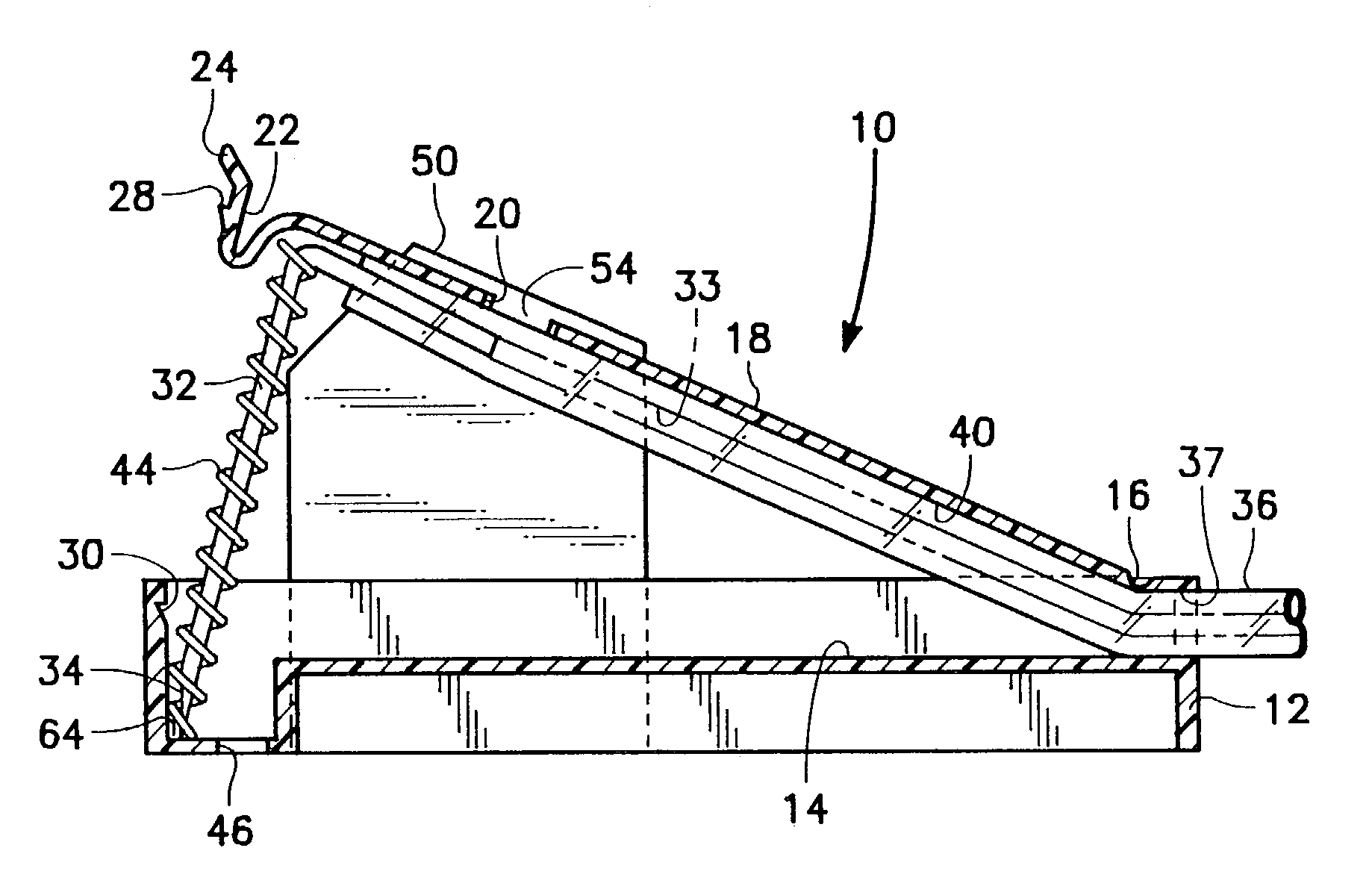
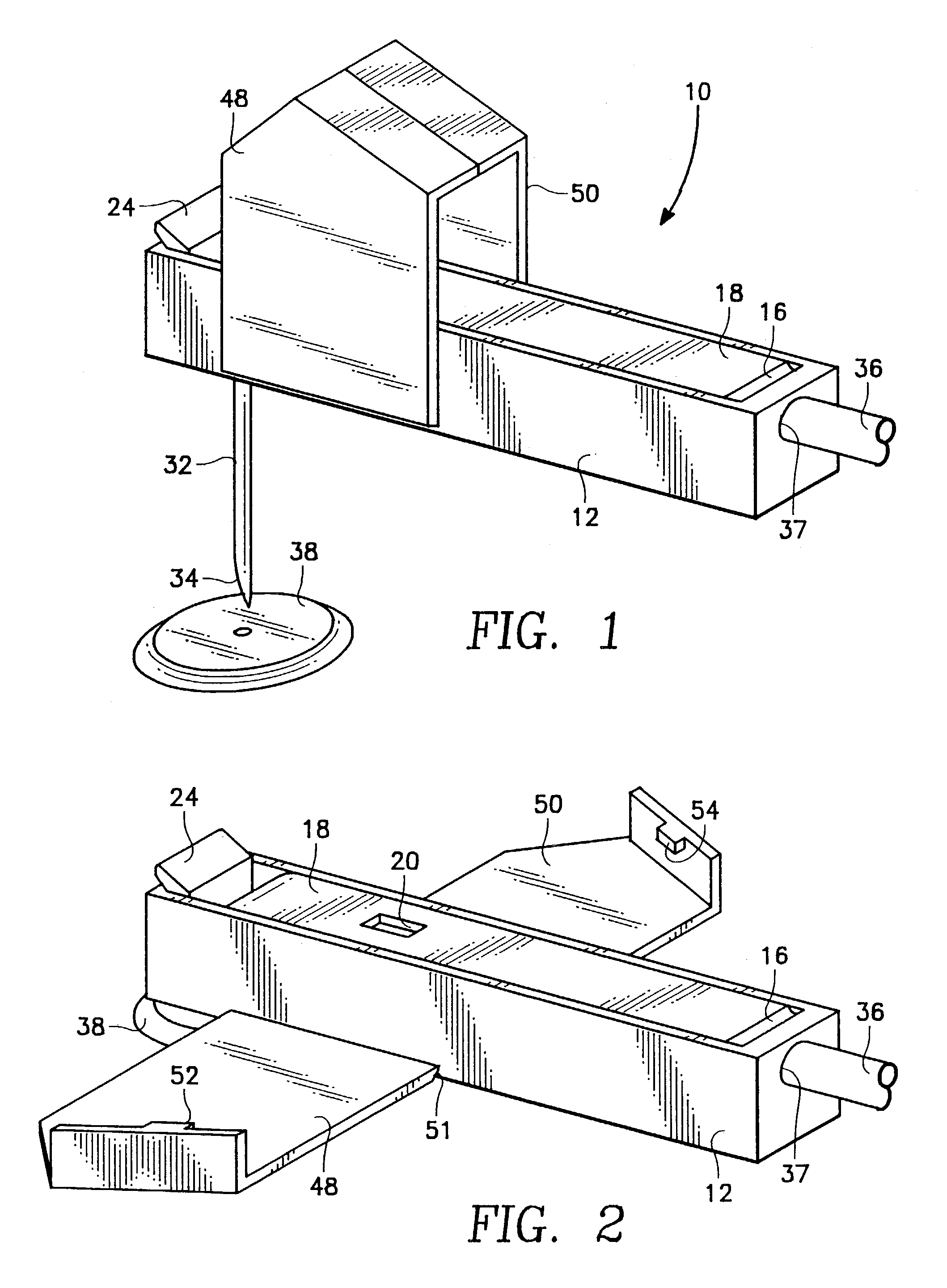
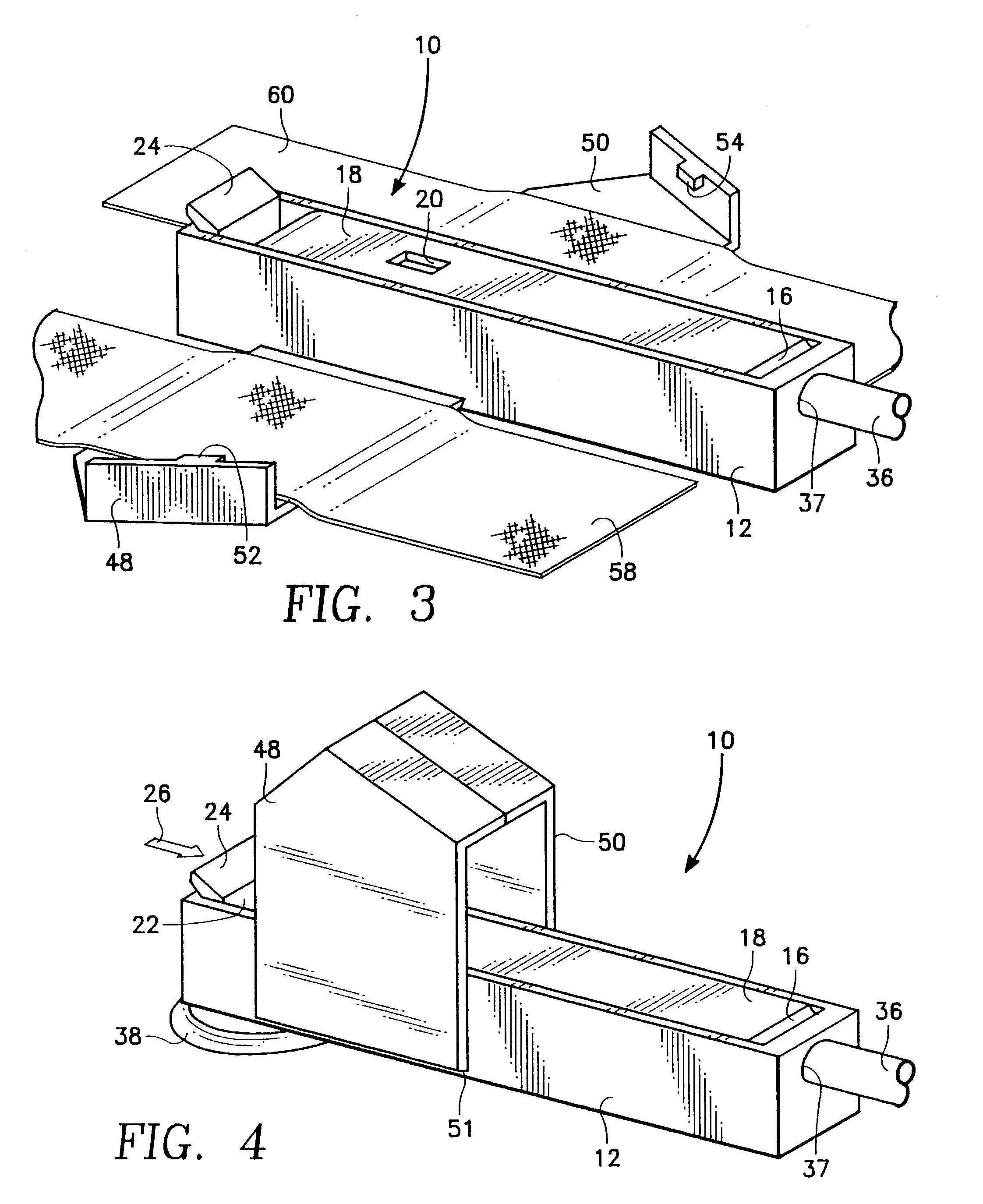
[0033]Referring particularly to the drawings, there is shown the automatic retraction Huber needle enclosure 10 of this invention. The enclosure 10 includes an elongated fixed housing 12. The fixed housing 12 has an internal chamber 14. The fixed housing 12 will normally be constructed of a sheet plastic material. Integrally connected by a living hinge 16 to the aft end of the fixed housing 12 is a lid 18. The lid 18 has formed therein a through slot 20. The slot 20 is located intermediate the ends of the lid 18. The forward end of the lid 18 is formed into a latch 22 which is to lock the Huber needle 32 in the extended position, as is shown in FIGS. 1, 7 and 8. The latch 22 is deflectable by applying of an inward pressure against handle 24 in the direction of arrow 26 in FIG. 4. The application of pressure in the direction of arrow 26 will cause the latch 24 to be deflected sufficiently to disengage protrusion 28 from indentation 30 formed within the fixed housing 12.

[0034]The Hube...


PUM


Abstract

An automatic retraction Huber needle safety enclosure which is designed principally for a Huber needle. A Huber needle is a hypodermic needle that is in the shape of a right angle. The safety enclosure has an internal chamber which is formed between a housing and a lid with the lid being movable relative to the housing between a closed position and an open position. The Huber needle is mounted within the internal chamber. The Huber needle is movable between an extended position and a retracted position. With the Huber needle in the extended position, the Huber needle is capable of being inserted within the body of a human or animal. With the Huber needle in the retracted position, the tip of the Huber needle is to be totally confined within the internal chamber. A wing assembly is attached to the housing which functions to facilitate securement of the safety enclosure to the body of the animal or human and forming an enclosure with the wing assembly folded in abutting juxtaposition.

Description

BACKGROUND OF THE INVENTION[0001]1. Field of the Invention[0002]This invention is related to a safety enclosure for a Huber needle in order to keep the Huber needle from inadvertently sticking a medical practitioner during installing and removal of the Huber needle in conjunction with an animal body which includes humans.[0003]2. Description of the Related Art[0004]Within the medical field, more and more patients require the use of vascular access devices as part of their care. Vascular access devices (implanted ports) are used on human patients to supply pain drugs, chemotherapy, antibiotics, anti-viral or anti-fungal drugs as well as for hydration and nutrition. In recent years, there has been a substantial increase in the number of patients with implanted ports. An implanted port requires a special needle to be inserted through the skin of the patient and into the port. The most common type of such a needle includes a ninety degree bend. This type of needle is called a Huber need...

Claims


Application Information

Patent Timeline
IPC IPC(8): A61M5/158A61M5/178A61M5/32A61M25/06
CPCA61M5/158A61M25/0631A61M5/3257A61M25/0612A61M2005/1581A61M2005/1583A61M2205/8281Y10S128/919
Inventor HALSETH, THOR R.
Owner CR BARD INC
Learn More