Prosthetic element comprising two components and process for assembling such a prosthetic element

a technology of prosthetic elements and components, applied in the field of prosthetic elements, can solve the problems of not always being able to achieve the effect of reducing the risk of thread distortion or tapping, and avoiding the possibility of affecting the quality of the prosthetic elemen

Inactive Publication Date: 2005-11-29
TORNIER SA SAINT ISMIER
View PDF15 Cites 125 Cited by
  • Summary
  • Abstract
  • Description
  • Claims
  • Application Information

AI Technical Summary

Benefits of technology

[0009]Thanks to the invention, the locking screw may be immobilized with respect to one of the principal components, this guaranteeing its positioning and orientation with respect thereto. Then, when its guide finger is inserted in the housing of the second component which has a transverse section corresponding to that of the finger, the components are guided with

Problems solved by technology

The known devices require precise positioning and alignment of the components constituting a prosthetic element, which is not always possible as the operative field is difficult to access and as it is delicate to visualize due to the traumatic depression

Method used


Image

  • Prosthetic element comprising two components and process for assembling such a prosthetic element
  • Prosthetic element comprising two components and process for assembling such a prosthetic element
  • Prosthetic element comprising two components and process for assembling such a prosthetic element

Examples


Embodiment Construction

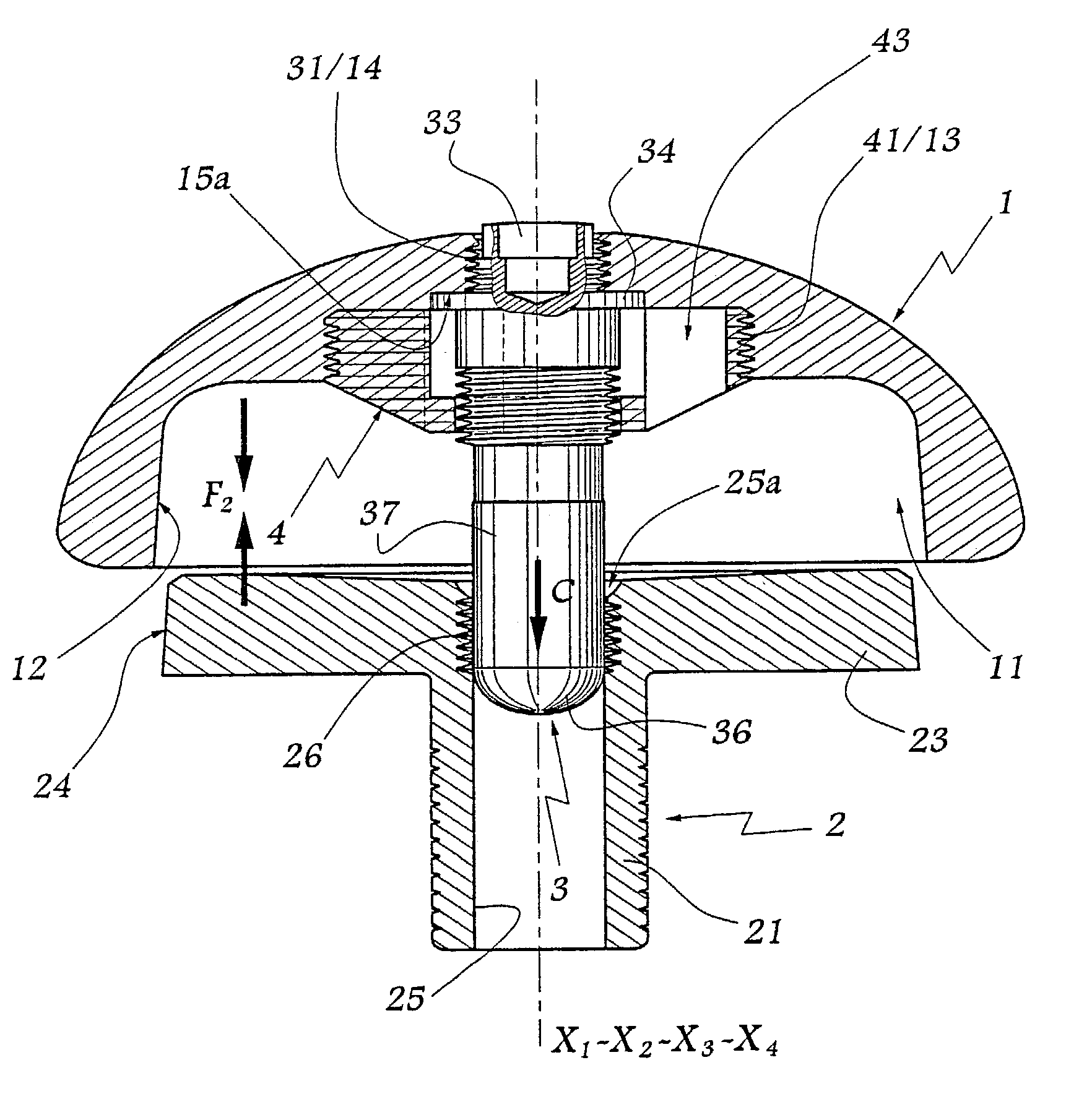
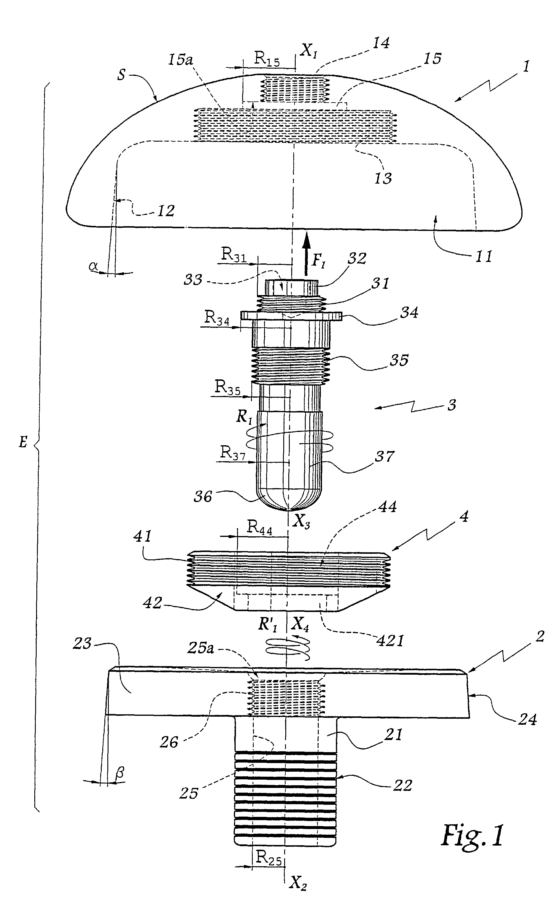
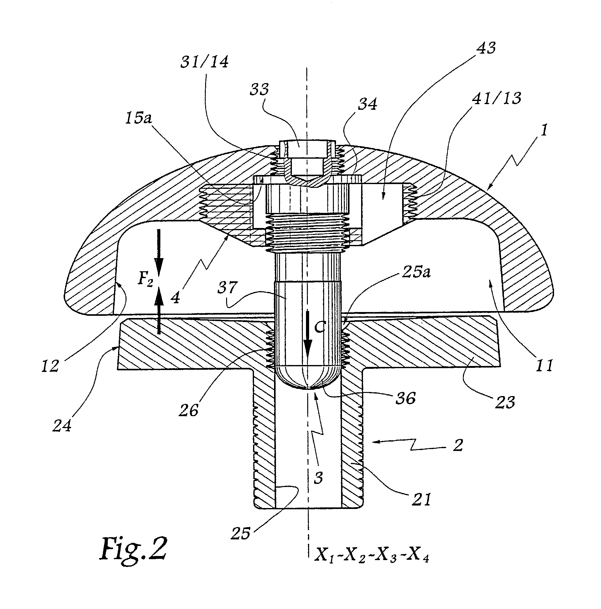
[0039]Referring now to the drawings, the prosthetic element E shown in the Figures is intended to be mounted on a shoulder in order to constitute an articular surface S intended to cooperate with a cupule (not shown) belonging to a complementary prosthetic element anchored in the patient's humerus.

[0040]The surface S is approximately in the form of a portion of sphere and constitutes the outer surface of a first principal component 1 made of a material compatible with the movements of articulation on the cupule associated therewith.

[0041]X1 denotes a central axis of the component 1 which constitutes a diameter of the surface S. The component 1 is provided with a central recess 11 centered on axis X1 and of which 12 denotes the peripheral surface, this surface being of truncated shape.

[0042]A tapping 13 is provided at the bottom of the recess 11, centered on axis X1.

[0043]A second tapping 14 is centered on axis X1 and opens to the outside, at the surface S.

[0044]A circular bore 15 is...


PUM


Abstract

A prosthetic element comprising two principal components which are assembled together and immobilized with respect to each other by a screw which may be selectively threaded into at least one tapping in at least one of the principal components. The screw comprises at least one radial element adapted to abut against a stop surface within the first component, and a non-threaded end forming a guide which is adapted to slide in a bore in the second component.

Description

BACKGROUND OF THE INVENTION[0001]1. Field of the Invention[0002]The present invention relates to a prosthetic element comprising two principal components, to the use of such an element, and to processes for assembly of such an element.[0003]2. Description of the Related Art[0004]A prosthetic element most often comprises a part intended to constitute an articular surface and a part for anchorage in the patient's bone. Taking into account their respective mechanical functions, these parts are sometimes composed of distinct components, such components each being optimalized as far as the choice of their constituent materials and their mode of manufacture are concerned. These components should then be able to be assembled precisely and easily. For example, an anchoring component may be fixed in the bone and a component forming an articular surface added thereon.[0005]In certain prior art devices, such as disclosed in FR-A-2 605 514 for example, it is known to use a screw for locking one...

Claims


Application Information

Patent Timeline
IPC IPC(8): A61F2/00A61F2/30A61F2/40A61F2/46
CPCA61F2/30721A61F2/4081A61F2/4637A61F2/30771A61F2002/30138A61F2002/30224A61F2002/30233A61F2002/30235A61F2002/30329A61F2002/30332A61F2002/30354A61F2002/30372A61F2002/30405A61F2002/30433A61F2002/30438A61F2002/30507A61F2002/30512A61F2002/30574A61F2002/30593A61F2002/30604A61F2002/30774A61F2002/3079A61F2002/30795A61F2002/30822A61F2002/30827A61F2002/30878A61F2002/4085A61F2002/4638A61F2220/0025A61F2220/0033A61F2220/0041A61F2230/0017A61F2230/0069
Inventor TORNIER, ALAIN
Owner TORNIER SA SAINT ISMIER
Why Eureka
Try Eureka