Electrical connector

a technology of electrical connectors and connectors, applied in the direction of coupling device connections, insulating bodies, tumbler/rocker switches, etc., can solve the problems of link flexing and breaking, time-consuming and labor-intensive installation, and difficulty in clamping jaws

Inactive Publication Date: 2005-11-29
GEORGE DAVID M
View PDF4 Cites 9 Cited by
  • Summary
  • Abstract
  • Description
  • Claims
  • Application Information

AI Technical Summary

Problems solved by technology

When a particular connector receptacle is to be used, the cover is pried away from the wall which causes the link to flex and break.
First, it is time-consuming and labor intensive to install.
Second, the clamping of the jaws can be difficult due to placement of the box in relation to the structure being wired.
That is, the clamping screws may be awkward or essentially impossible to access for tightening after the box is assembled, installed and the cable is inserted through the connector.
Thirdly, because it is made of metal and the jaws can be tightened too much, the clamp can penetrate the cable jacket and short circuit the conductors.
This is unsightly and can lead to wear and deterioration of the structure finished wall.
While the “Hit-lock” connectors are non-conductive and do not have vise-jaw style, screw-threaded clamps, they do not overcome all of the above listed disadvantages of the “Romex” connectors.

Method used


Image

  • Electrical connector
  • Electrical connector
  • Electrical connector

Examples


Embodiment Construction

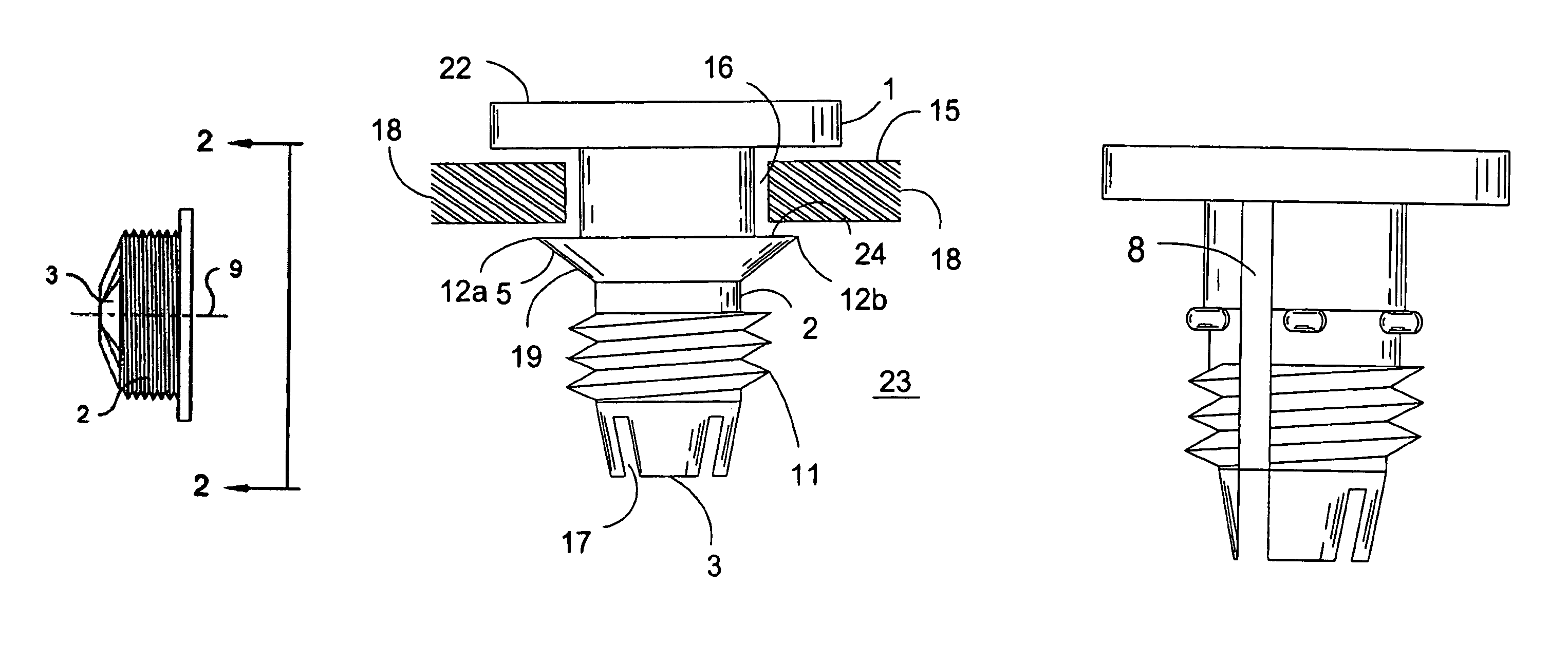
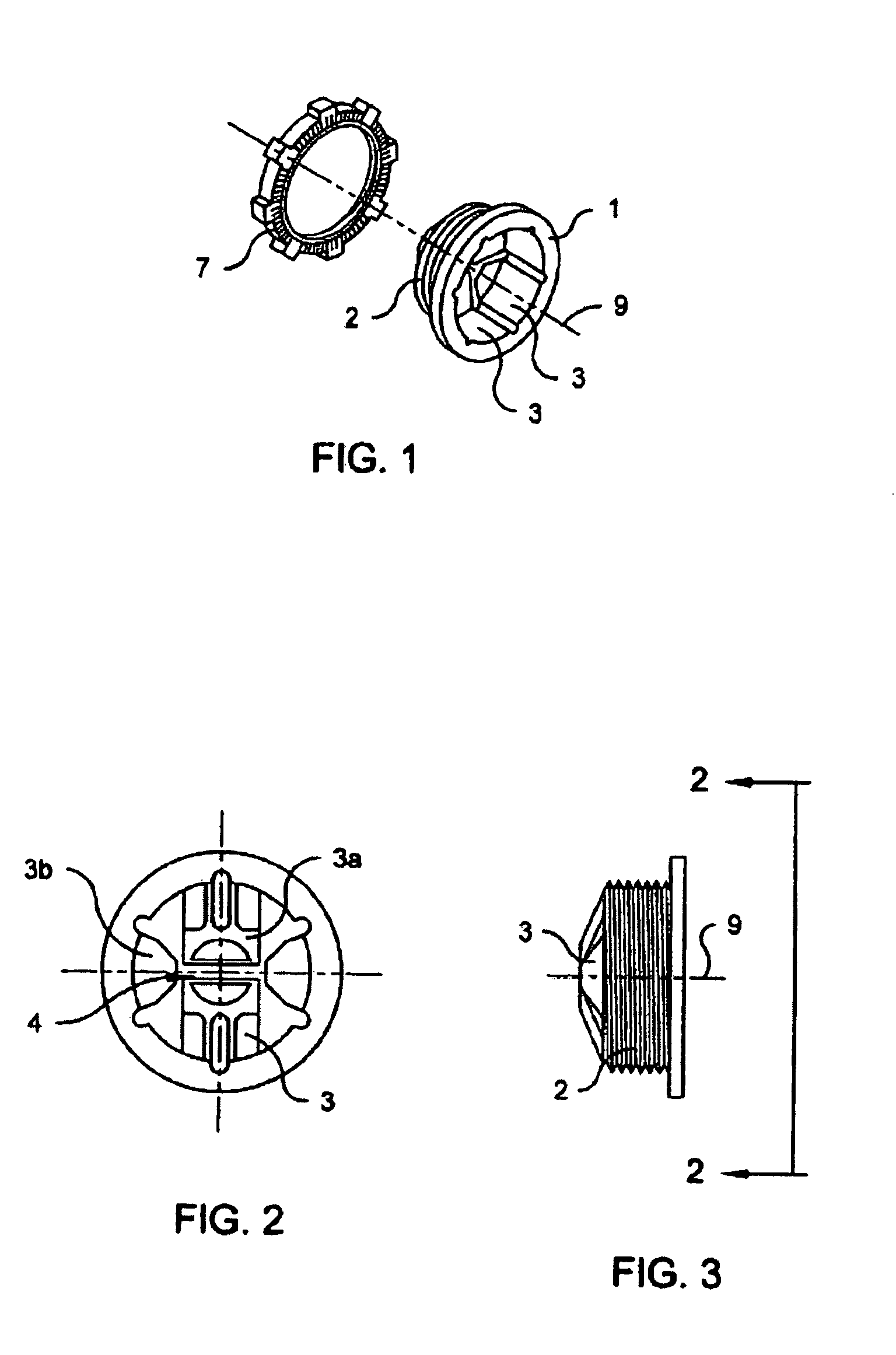
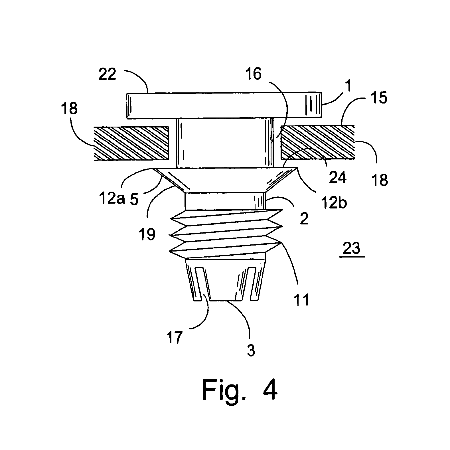
[0017]The present invention is a novel, preferably non-conducting, non-metallic electrical connector that allows wire or cable to be inserted into a junction box, but prevents its reversible movement. One preferred embodiment of the electrical connector is illustrated in FIG. 1–FIG. 3. This connector comprises a cylindrical body 2 having external male screw threads, a butt flange 1 at one end, and a cable immobilizer at the other end. The cable immobilizer comprises prongs 3 adapted to prevent the reversible axial movement of the insulated wire or cable to be held by the prongs.

[0018]FIG. 1 illustrates an embodiment where the butt flange is a circular flange. When a circular flange is utilized, the diameter of the flange should be larger than the diameter of a standard threaded hole in a standard junction box. With this configuration the connector can be screwed into the junction box up until the point where the flange fits tightly against the wall of the junction box. The shape of ...


PUM


Abstract

An electrical connector for clamping a cable to an electrical junction box. The connector has a cylindrical body with a flange at one end and a male threaded portion adapted to mate with the threads of a female connector receptacle on the box. The connector includes a cable immobilizer that receives the cable inserted into the box from the flanged end of the connector and which bites into the cable insulation such that the cable cannot be withdrawn after insertion. In a preferred aspect the connector has radially extending protrusions which in concert with the end flange allow the connector to insert into and lock in a non-threaded, knock-out style connector receptacle.

Description

FIELD OF THE INVENTION[0001]This invention relates to electrical connectors to hold and stabilize insulated wire and cable in electrical junction boxes.BACKGROUND OF THE INVENTION[0002]Electrical codes generally require that wire or cable entering junction boxes be clamped and thus immobilized to prevent connections from loosening and accidentally causing a disconnect. Clamping also prevents insulation jackets from being chafed by moving contact with exposed portions of the junction box, and thereby reduces the risk of electrical short circuits and associated damage.[0003]This invention is primarily concerned with connections to standard electrical junction boxes for nominally 110–220 volt, alternating current electrical service in residential, commercial and light industrial electric power supply service. Outdoor, weather-exposed junction boxes typically have one or more connector receptacles formed by a built-up boss in the box wall. The boss is usually drilled and female screw th...

Claims


Application Information

Patent Timeline
Patent Type & Authority Patents(United States)
IPC IPC(8): H02G3/06H02G3/08H02G3/18
CPCH02G3/0658H02G3/088
Inventor GEORGE, DAVID M.
Owner GEORGE DAVID M
Why Eureka
Try Eureka