
Slot motor including legs engaging openings of circuit breaker housing and electrical switching apparatus employing the same

a technology of slot motors and circuit breakers, which is applied in the direction of circuit breakers, contact mechanisms, dynamo-electric relays, etc., to achieve the effect of increasing the strength of the circuit breaker housing

Inactive Publication Date: 2005-11-29
EATON CORP
View PDF12 Cites 13 Cited by
  • Summary
  • Abstract
  • Description
  • Claims
  • Application Information

AI Technical Summary

Benefits of technology

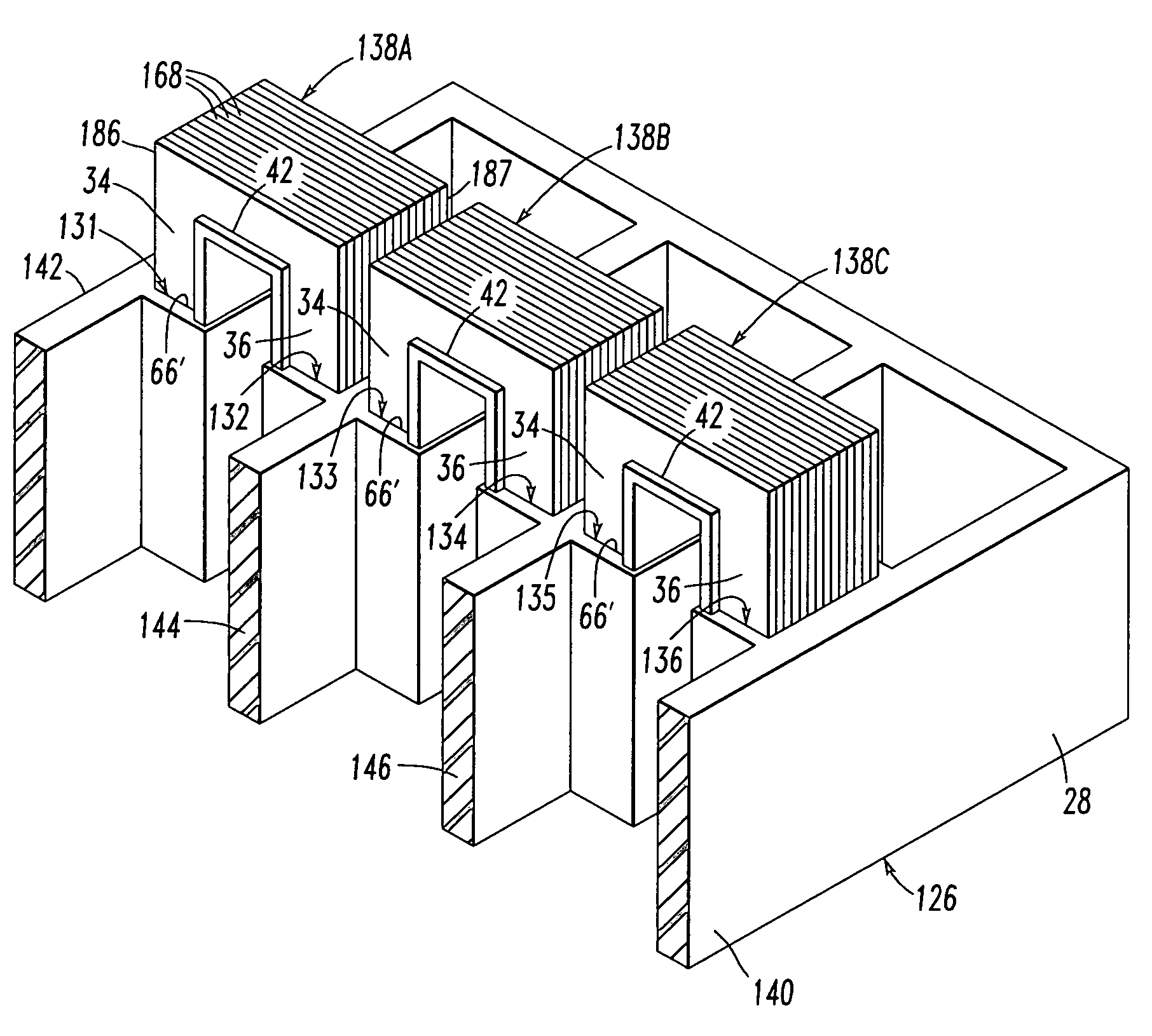
[0009]These needs and others are met by the present invention which employs the rigid legs of a slot motor to reinforce the exterior walls of a circuit breaker housing. In addition to increasing the strength of the circuit breaker housing, this structure reduces parts, since it eliminates a corresponding slot motor housing assembly and, instead, employs the circuit breaker housing.
[0017]The first and second interior walls of the housing in combination with the first and second legs may limit motion of the first and second exterior walls, respectively, of the housing during interruption of a power circuit when the separable contacts move from the closed position to the open position in response to the trip mechanism. The first and second interior walls of the housing in combination with the first and second legs may enable the first and second exterior walls, respectively, of the housing to withstand pressure within the housing during interruption of the power circuit.

Problems solved by technology

The exterior walls of molded case circuit breakers have typically been a weak link for case strength and a limiting factor in increasing the interrupting ratings of circuit breakers.

Method used


Image

  • Slot motor including legs engaging openings of circuit breaker housing and electrical switching apparatus employing the same
  • Slot motor including legs engaging openings of circuit breaker housing and electrical switching apparatus employing the same
  • Slot motor including legs engaging openings of circuit breaker housing and electrical switching apparatus employing the same

Examples


example 1

[0038]Non-limiting examples of the thicknesses 78, 80 and 82 are 0.200″, 0.250″ and 0.060″ (minimum), respectively.

example 2

[0039]Alternatively, the second thickness 80 of the magnetic member legs may be less than the first thickness 78 of the exterior walls.

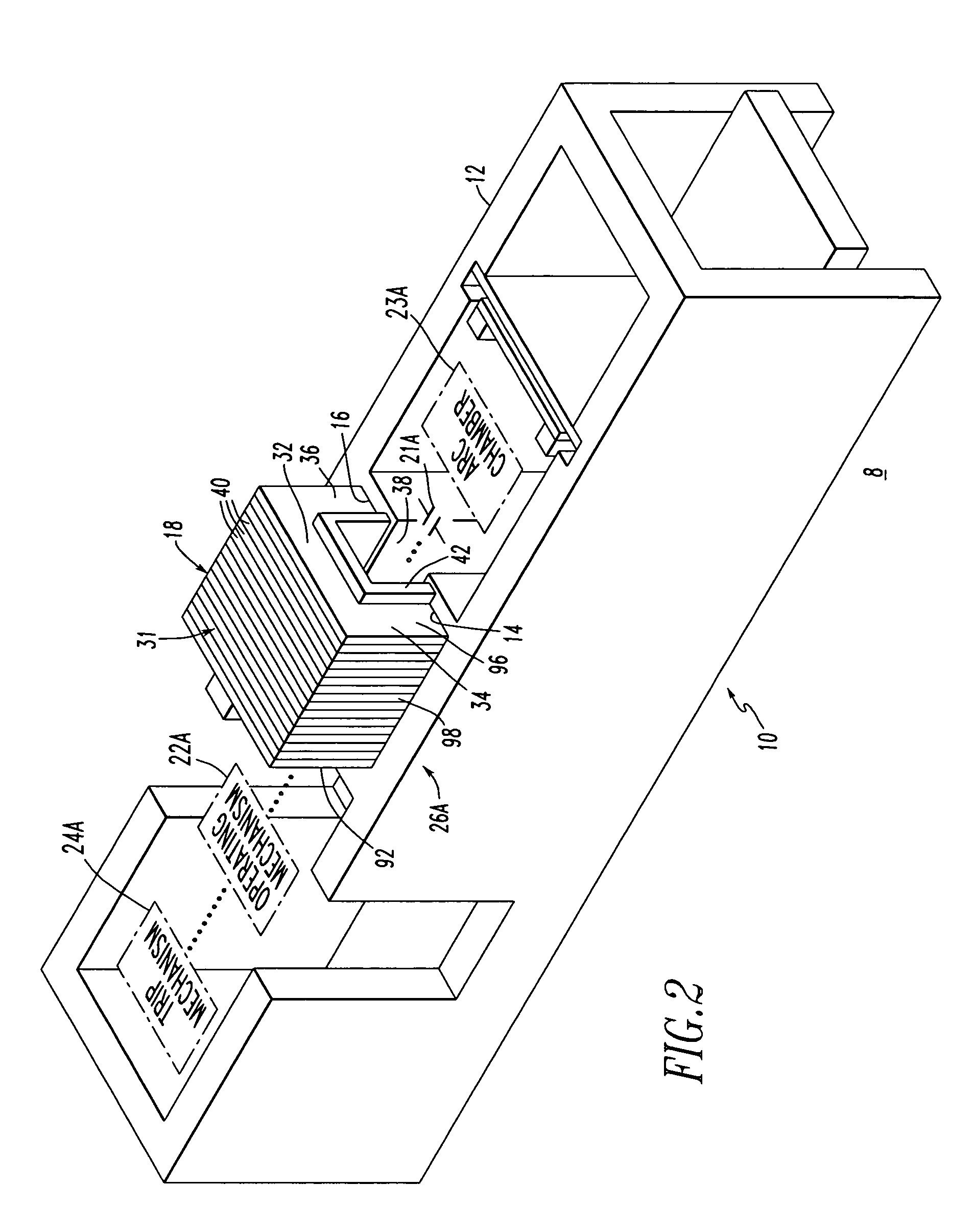
[0040]Each of the first and second openings 14,16 of FIG. 5 has four sides 84,86,88,90. For example, the three first interior walls 62,64,66 and the interior surface of the first exterior wall 68 define the four sides of the first opening 14. Similarly, the three second interior walls 70,72,74 and the interior surface of the second exterior wall 76 define the four sides of the second opening 16. The first and second legs 34,36 of the magnetic member 31 of FIG. 2 include four sides 92,94,96,98 (generally shown in FIG. 2, with side 94 shown in FIG. 3), which engage the four sides 84,86,88,90 of the first and second openings 14,16 (as shown with the opening 14 of FIG. 5), in order to reinforce and add rigidity to the first and second exterior walls 68,76, respectively.

[0041]Referring to FIG. 6, a three-phase circuit breaker molded housing 100 includes a...


PUM


Abstract

A circuit breaker includes a housing having first and second openings, with stationary and movable separable contacts disposed therein. An operating mechanism is disposed in the housing, is coupled to the separable contacts and is structured to move those contacts between open and closed positions. A trip mechanism is disposed in the housing and cooperates with the operating mechanism to trip open the separable contacts. A slot motor assembly is disposed about the separable contacts and has upper and lower slot motor portions. The upper slot motor portion is disposed above the movable contact and the lower slot motor portion is disposed below the stationary contact. The upper slot motor portion includes a rigid, laminated steel member having a general U-shape, with a bight portion, and first and second legs. The first and second legs engage the housing at the respective first and second openings.

Description

BACKGROUND OF THE INVENTION[0001]1. Field of the Invention[0002]The present invention relates to electrical switching apparatus, such as, for example, circuit breakers and, more particularly, to circuit breakers employing a slot motor.[0003]2. Background Information[0004]Circuit breakers, such as molded case circuit breakers, include at least one pair of separable contacts. A first contact is fixed within the molded case housing and a second movable contact is coupled to an operating mechanism. These separable contacts are in electrical communication with either the line or the load coupled to the circuit breaker. The operating mechanism moves the movable contact between a first, open position wherein the movable contact is spaced from the fixed contact, and a second, closed position wherein the fixed and movable contacts are in contact and electrical communication. The operating mechanism may be operated manually or by a trip mechanism.[0005]The exterior walls of molded case circui...

Claims


Application Information

Patent Timeline
Patent Type & Authority Patents(United States)
IPC IPC(8): H01H71/02H01H77/10
CPCH01H71/0257H01H77/108
Inventor MUELLER, ROBERT W.WHITAKER, THOMAS A.
Owner EATON CORP
Learn More