Antenna apparatus

Inactive Publication Date: 2005-11-29
KK TOSHIBA
View PDF10 Cites 0 Cited by
  • Summary
  • Abstract
  • Description
  • Claims
  • Application Information

AI Technical Summary

Benefits of technology

[0013]An object of the present invention is to provide an antenna apparatus capable of achieving compatibility between a reduction in mounting area and an increase in frequency band of a matching circuit thereof.
[0021]A dielectric may be inserted between the metal conductor piece and one side of the cavity. In this case, the dielectric serves to increase the capacitance of the metal conductor piece. If the capacitance increases, the physical length of the linear element can be shortened further, and the mechanical strength between the metal conductor piece and the cavity can be increased.

Problems solved by technology

Even in the half-wave antenna, however, current is likely to flow into the cavity to make it impossible to form a desired pattern depending on the configuration of a matching circuit.
However, there is a problem that current leaks from a feeder point to a cavity when the quarter-wave-length element is inserted between the half-wave antenna and the feeder point.
Such a leakage current causes unnecessary electric wave emitted from the cavity.
However, the antenna apparatus shown in FIG. 8, of which the quarter-wave-length element serving as a matching circuit has to be encased in a plastic cavity of a cellular phone, the quarter-wave-length element becomes relatively long depending on the frequency and thus requires a large area when it is inserted in the cavity of a cellular phone that steadily decreases in size.
Further, the wide-band characteristics of the quarter-wave-length element are likely to deteriorate.

Method used


Image

  • Antenna apparatus
  • Antenna apparatus
  • Antenna apparatus

Examples


second embodiment

(Second Embodiment)

[0063]FIGS. 5A to 5C are views of an antenna apparatus according to a second embodiment of the present invention. In the second embodiment, a dielectric 80 is inserted between a metal conductor piece 7 and a cavity 1. As shown in the equivalent circuit diagram of FIG. 5C, the dielectric 80 is connected in parallel with the metal conductor piece 7 and serves to increase the capacitance between the cavity 1 and the metal conductor piece 7. If the capacitance is increased, the length of a λ / 4 element 3, which is in inverse proportion to the capacitance, can be decreased further.

[0064]If, moreover, the dielectric 80 is inserted between the metal conductor piece 7 and the cavity 1, a physical connection between the metal conductor piece 7 and cavity 1 can be secured to protect the antenna apparatus from a shock or the like. In the example of FIGS. 5A to 5C, the metal conductor piece 7 and dielectric 80 are both square poles; however, they can be formed like a plate as ...


PUM


Abstract

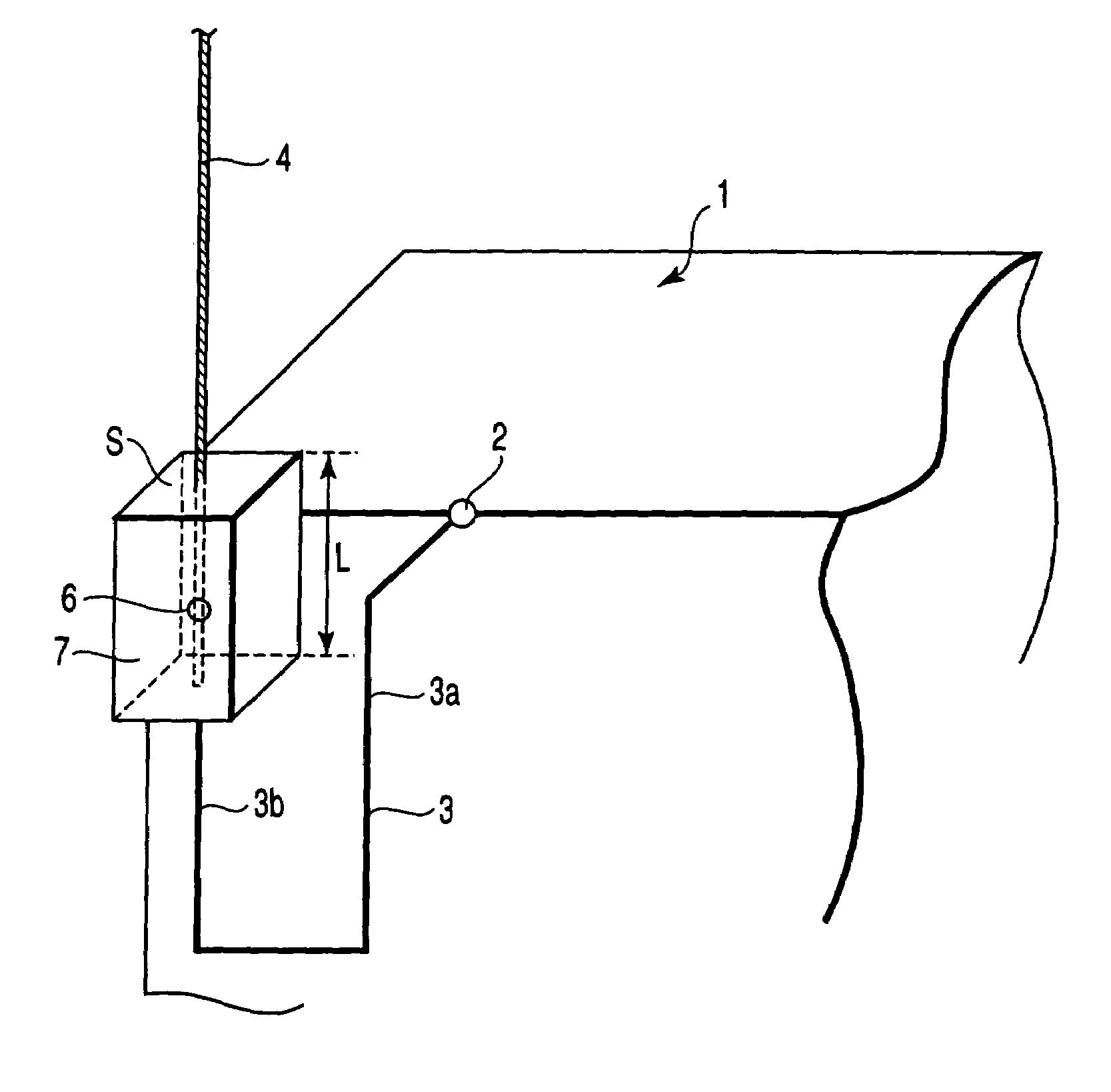
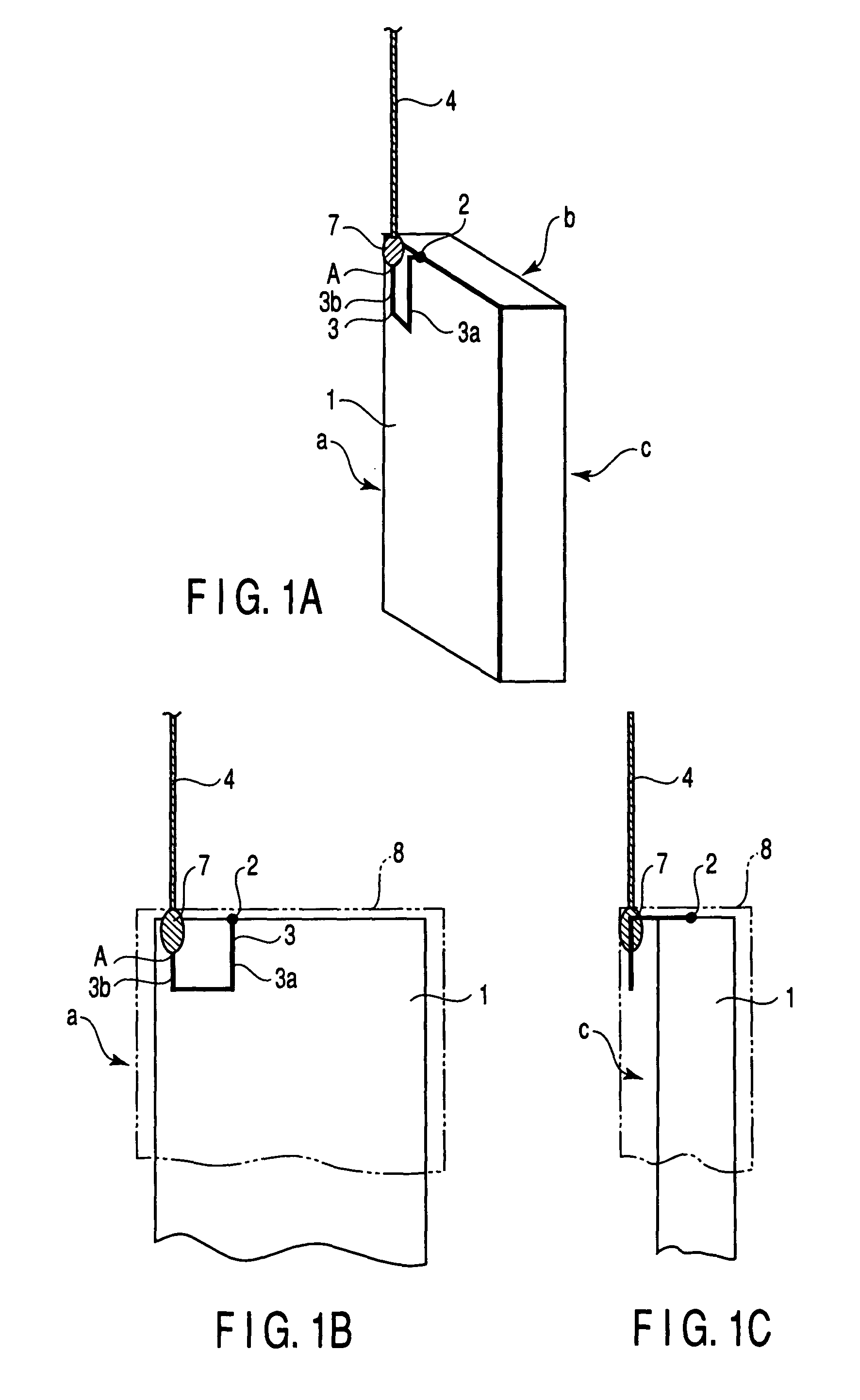
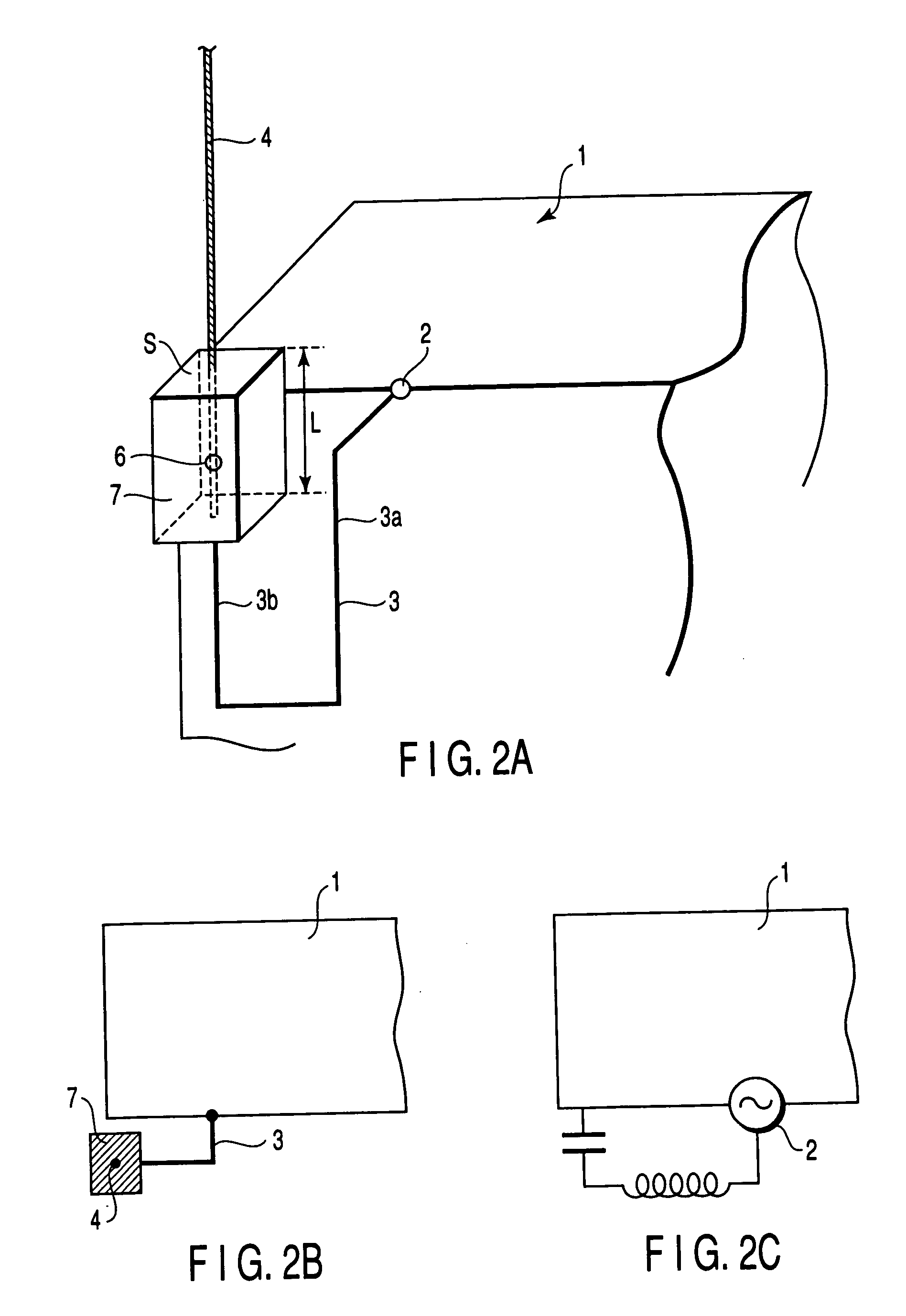
An antenna apparatus coupled to a feeding point arranged on a cavity is disclosed. The apparatus includes a linear element extending from the feeding point and having a physical length that is shorter than a one-quarter wavelength. A half-wave antenna element is connected to an end of the linear element. The apparatus also includes a metal conductor piece including a connecting point between the linear element and the half-wave antenna element and located close to one surface of the cavity. The linear element includes a first portion extending in a first direction opposite to that of the half-wave element from the feeding point and in parallel with one surface of the cavity and a second portion extending in a second direction, which is equal to a direction in which the half-wave antenna element extends, and in parallel with one surface of the cavity.

Description

CROSS-REFERENCE TO RELATED APPLICATIONS[0001]This application is based upon and claims the benefit of priority from the prior Japanese Patent Application No. 2000-296964, filed Sep. 28, 2000, the entire contents of which are incorporated herein by reference.BACKGROUND OF THE INVENTION[0002]1. Field of the Invention[0003]The present invention relates to an antenna apparatus of a portable radio terminal having a radio function.[0004]2. Description of the Related Art[0005]In a portable radio terminal including an antenna and a radio that are integrated as one component, the directivity of the antenna is likely to vary with the shape of a cavity.[0006]It is known that the use of a half-wave (λ / 2) antenna reduces current flowing from a feeder line to a cavity. If a half-wave linear antenna is employed, an influence of a cavity is reduced, which is convenient for the design of an antenna system.[0007]Even in the half-wave antenna, however, current is likely to flow into the cavity to make...

Claims


Application Information

Patent Timeline
IPC IPC(8): H01Q1/24H01Q1/32H01Q9/30H01Q9/32
CPCH01Q1/242H01Q9/32
Inventor SEKINE, SHUICHIWATANABE, HIROSHINODA, MOTOJIODACHI, NORIAKI
Owner KK TOSHIBA
Why Eureka
Try Eureka