Circuit Device, Electronic Apparatus And Power Supply Circuit

Inactive Publication Date: 2011-09-22
SEIKO EPSON CORP
View PDF8 Cites 8 Cited by
  • Summary
  • Abstract
  • Description
  • Claims
  • Application Information

AI Technical Summary

Benefits of technology

[0010]In accordance with an advantage of some aspects of the invention, circuit devices, electronic

Problems solved by technology

When diodes are used in an adiabatic logic circuit, the power consumed by the diodes cannot be ignored.
While power supply voltages have been lowered due to the progress in miniaturization of semiconductor manufacturing process, voltage drops caused by diodes lower the voltage level of signals, and deteriorate the degree of noise margin.
However, when the power supply circuit that supplies power supply voltages to the adiabatic logic circuit does not perform power reg

Method used


Image

  • Circuit Device, Electronic Apparatus And Power Supply Circuit
  • Circuit Device, Electronic Apparatus And Power Supply Circuit
  • Circuit Device, Electronic Apparatus And Power Supply Circuit

Examples


Example

[0055]Preferred embodiments of the invention are described in detail below. It should be understood, however, that the embodiments described below shall not unduly limit the contents of the invention described in the scope of the claimed invention, and all of the compositions described in the embodiments would not necessarily be indispensable as means for solution of the invention.

1. Comparison Example

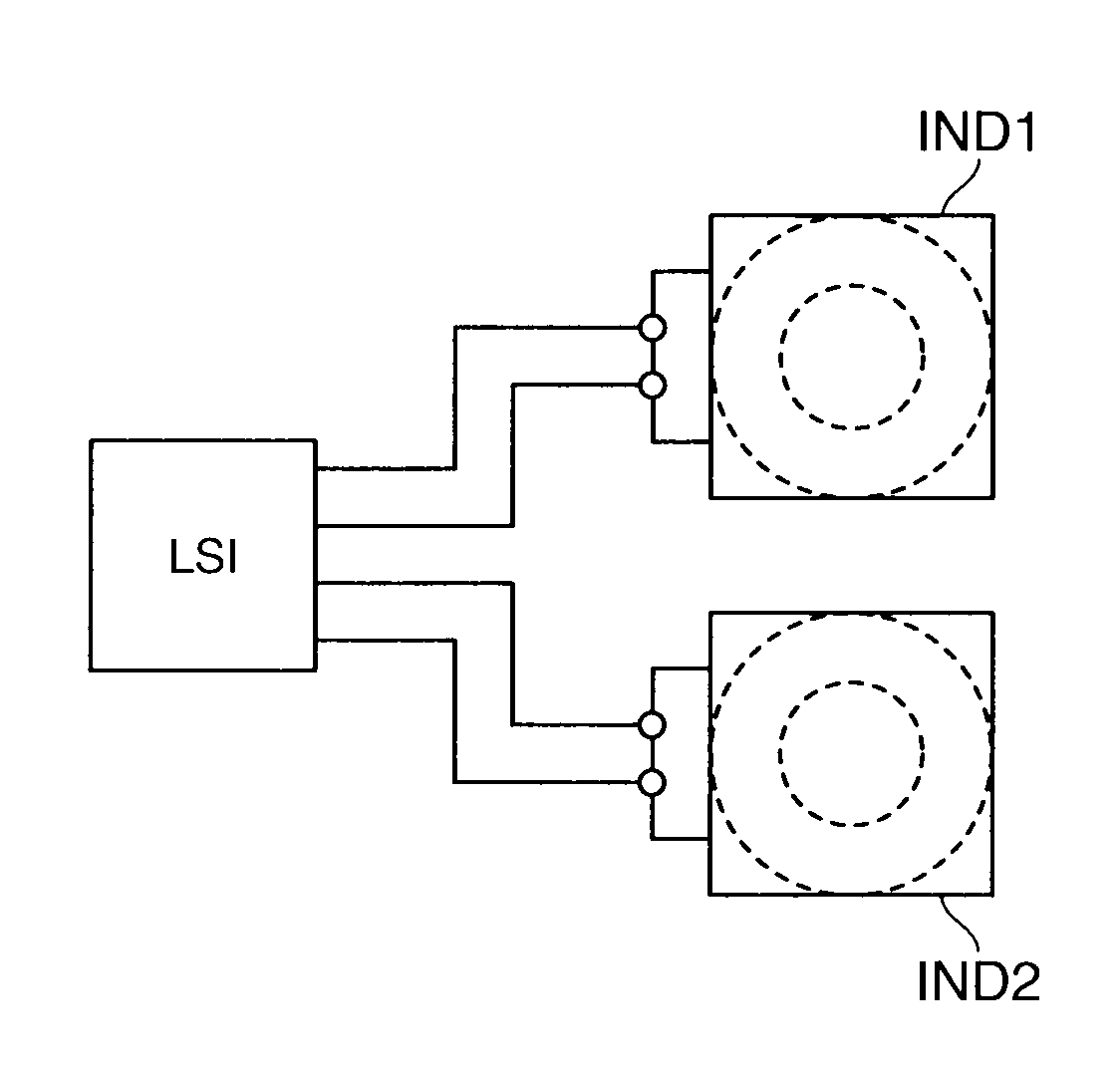
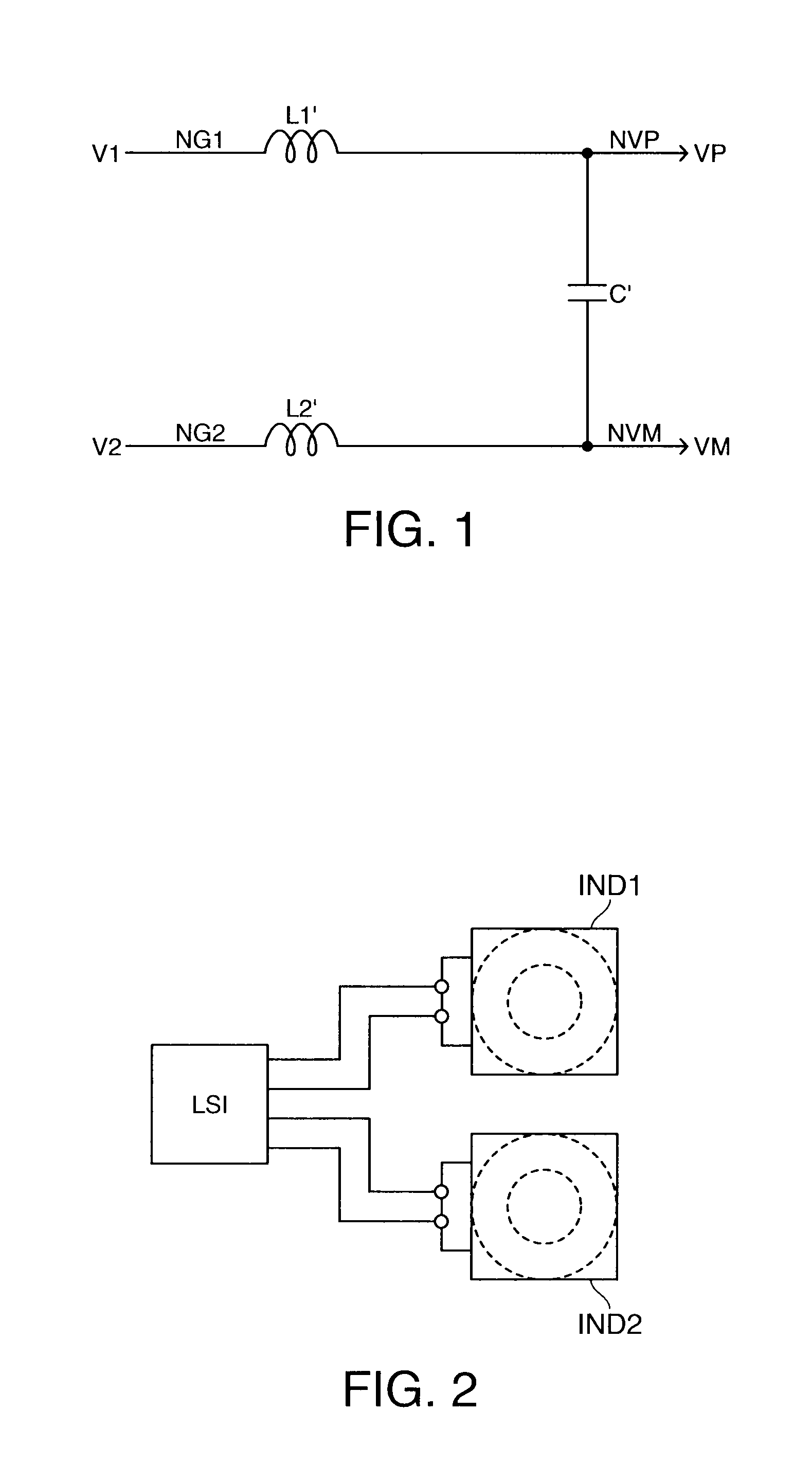
[0056]In accordance with an embodiment of the invention, a power supply circuit supplies a power supply voltage to an adiabatic logic circuit, and the power supply circuit performs power regeneration by a resonance circuit (for example, a power supply circuit 100 to be described below with reference to FIG. 7). In this case, if the power is regenerated by a resonance circuit formed from two coils and a capacitor, as described above, there is a problem in that the mounting area increases due to the two coils. This problem is described, using an example for comparison with an embodiment ...


PUM


Abstract

A circuit device includes a power supply circuit having a resonance circuit, and a logic circuit. The resonance circuit includes a first coil, and a second coil having a core section shared by the first coil. The logic circuit performs an adiabatic circuit operation with a power supply voltage generated by the resonance circuit.

Description

[0001]Priority is claimed on Japanese Patent Application No. 2010-061146, filed Mar. 17, 2010, the content of which is incorporated herein by reference.BACKGROUND[0002]1. Technical Field[0003]The invention relates to circuit devices, electronic apparatuses and power supply circuits.[0004]2. Related Art[0005]Adiabatic logic circuits are known as a technology to suppress power consumption of logic circuits (for example, the technology described in JP-A-2002-325031). The adiabatic logic circuit suppresses power consumption, which may be caused by the drain loss of transistors, by changing the power supply voltage. Also, a adiabatic logic circuit formed from CMOS static logic gates without using diodes, and a switched capacitor circuit that generates power supply clocks (for example, the technology described in JP-A-2009-278433) are known.[0006]When diodes are used in an adiabatic logic circuit, the power consumed by the diodes cannot be ignored. While power supply voltages have been lo...

Claims


Application Information

Patent Timeline
IPC IPC(8): H01F38/14
CPCH03H7/0115H03H2001/0057H03H7/09
Inventor SATO, HISAO
Owner SEIKO EPSON CORP
Why Eureka
Try Eureka