Electrochemical cell

Inactive Publication Date: 2007-01-30
SEIKO INSTR INC
View PDF1 Cites 5 Cited by
  • Summary
  • Abstract
  • Description
  • Claims
  • Application Information

AI Technical Summary

Benefits of technology

[0011]In consideration of the foregoing, an object of the present invention is to provide a terminal capable of reducing the mounting area of an electrochemical cell and avoiding whisker generation, and an electrochemical cell utilizing such terminal.

Problems solved by technology

The soldering to the circuit board has been executed with a soldering iron, but, as a result of reduction in dimensions and expansion of functions of the product, it has become necessary to mount a larger number of electronic components within a limited area circuit board and it has become difficult to secure space for inserting the soldering iron.
However, even if the electrochemical cell itself can be made smaller, it has been difficult to reduce the dimension of the terminals and still secure a stability and a peeling strength of soldering.
On the other hand, in case Sn or a Sn-alloy, free from Pb, is employed for such plating, whiskers are generated by the heat at the terminal welding and cause short circuiting.

Method used


Image

  • Electrochemical cell
  • Electrochemical cell
  • Electrochemical cell

Examples


example 1

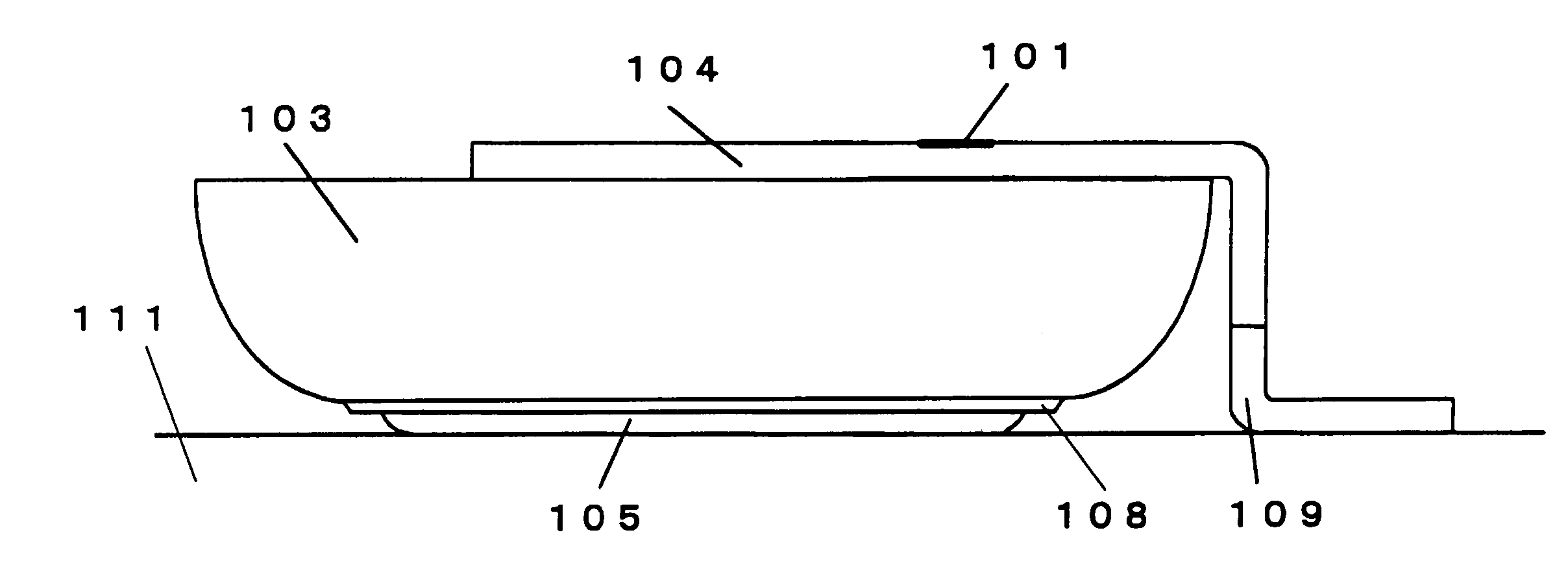
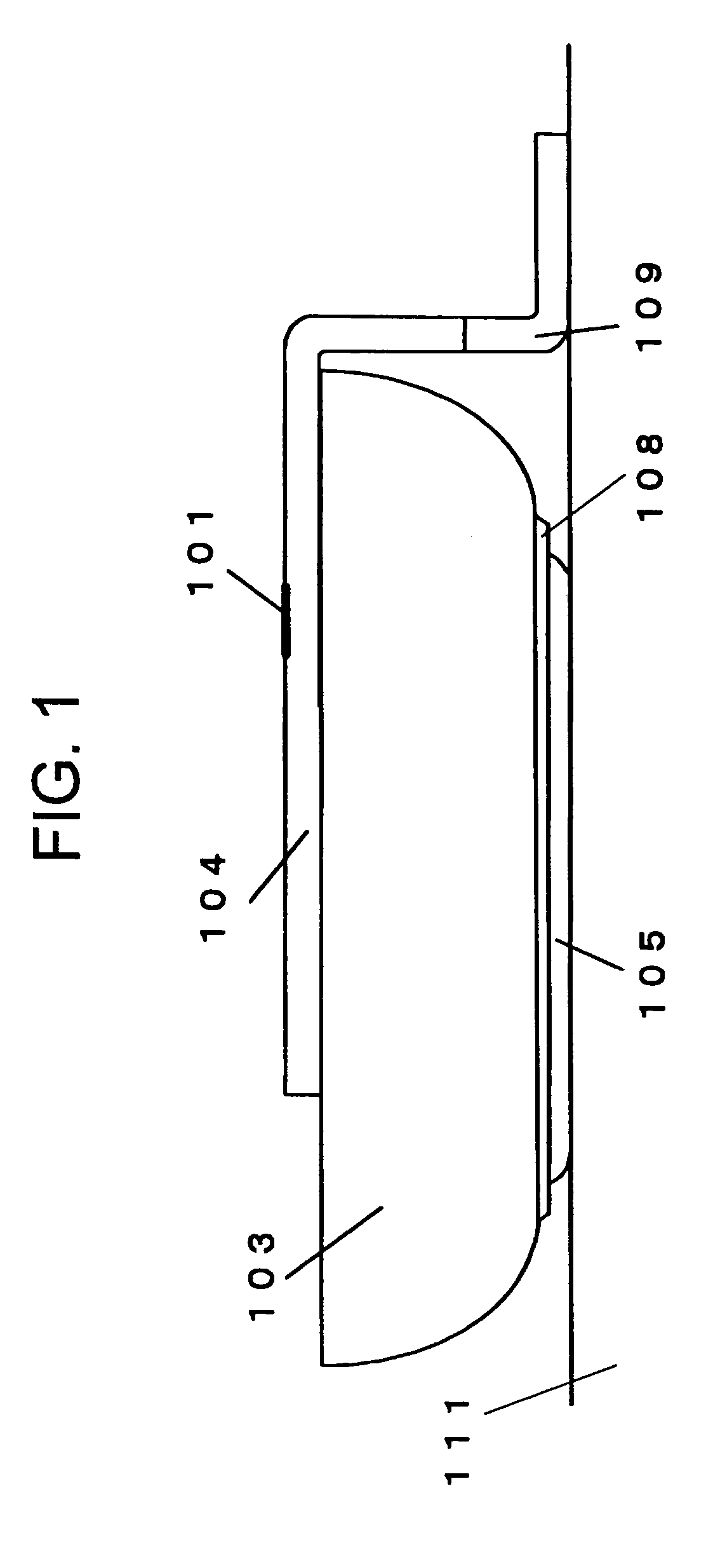
[0026]On a surface of a stainless steel plate (SUS 304) of a thickness of 0.15 mm, a Cu plating was applied with a thickness of 2 μm, and a solder plating of a Sn-alloy was applied thereon with a thickness of 5 μm. This stainless steel plate was made into the can for the negative pole, with the plated surface positioned at the outside of an electrochemical cell. The negative pole can thus formed was employed in preparing an electric double layer capacitor of 414 size. A gasket was constituted of PPS. On this electric double layer capacitor, a positive pole terminal of a width of 2 mm was laser welded. On the end portion of the positive pole terminal, a Cu plating was applied with a thickness of 2 μm, and a solder plated layer of a Sn-alloy solder was applied thereon with a thickness of 5 μm.

[0027]A cream solder was applied on a surface of a circuit board, coming into contact with the electric double layer capacitor of this example. The electric double layer capacitor was placed on t...

example 2

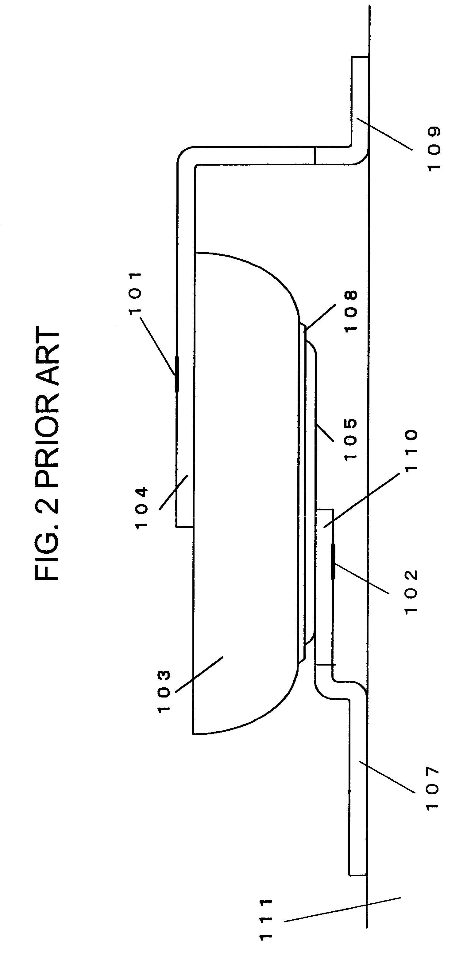
[0029]On a surface of a stainless steel plate (SUS 316) of a thickness of 0.10 mm, a Ni plating was applied with a thickness of 1 μm, and a Sn solder plating was applied thereon with a thickness of 5 μm. The stainless steel plate was made into the can for the positive pole, with the plated surface positioned at the outside of the electrochemical cell. The positive pole can thus formed was employed in preparing an organic electrolyte secondary battery of 414 size. A gasket was constituted of PEEK. On this organic electrolyte secondary battery, a negative pole terminal of a width of 2 mm was laser welded. On the end portion of the negative pole terminal, a Ni plating was applied with a thickness of 1 μm, and a Sn solder plated layer applied thereon with a thickness of 3 μm.

[0030]The height of the step 106 of the terminal was made larger by 0.1 mm than the height of the organic electrolyte secondary battery. Since the organic electrolyte secondary battery was prepared with a tolerance ...


PUM

PropertyMeasurementUnit
Heightaaaaaaaaaa

Abstract

An electrochemical cell capable of reflow soldering has a terminal for connection to a circuit board. The terminal is fixed to either the positive pole can or the negative pole can, and the bottom surface of the other pole can which is not fixed to the terminal is provided with a layer consisting of at least one of Au, Sn, Sn-alloy and Ni.

Description

BACKGROUND OF THE INVENTION[0001]1. Field of the Invention[0002]The present invention relates to an electrochemical cell such as a battery of button or coin type, or a capacitor.[0003]2. Description of the Background Art[0004]An electrochemical cell, such as a primary battery, a secondary battery or a capacitor of coin or button type, employed as a backup auxiliary power source for clock and memory functions of portable equipment, is usually utilized with two terminals mounted as positive and negative poles of the battery.[0005]With the recent progress in size reduction of components, there now are mounting boards with holes for terminals which are inserted in the top surface and soldered from the rear surface of the board (for example, cf. patent reference 1). Also, in a type widely employed recently, an electrochemical cell to which terminals are attached beforehand are simply placed on a board, and solder-plated end portions of the terminals are fixed by soldering to the top side...

Claims


Application Information

Patent Timeline
IPC IPC(8): H01M6/08H01M2/02H01G11/74B23K1/00H01G11/78H01M10/42H01M50/566
CPCB23K1/0008H01M10/425H01M2/30B23K2201/38B23K2101/38Y02E60/10H01M50/566
Inventor WATANABE, SHUNJIKANNO, YOSHIMISAKAI, TSUGIO
Owner SEIKO INSTR INC
Why Eureka
Try Eureka