Fluid mixing device

Inactive Publication Date: 2005-12-06
PPG ARCHITECTURAL FINISHES INC
View PDF77 Cites 16 Cited by
  • Summary
  • Abstract
  • Description
  • Claims
  • Application Information

AI Technical Summary

Benefits of technology

[0015]In an alternative embodiment of the invention, the mixing device includes the vanes arranged so that the inner edges of the vanes define a frusto-conical surface, in order to prevent clogging of paint within the mixing device. In one embodiment, the outer edges of the vanes are aligned generally parallel with or angled relative to a central axis of the mixing device, and the inner edges of the vanes are tapered to form the frusto-co

Problems solved by technology

In general, existing mixing devices suffer from several drawbacks when used to mix paint, most notably inefficient mixing and possible clogging.

Method used


Image

  • Fluid mixing device
  • Fluid mixing device
  • Fluid mixing device

Examples


Example

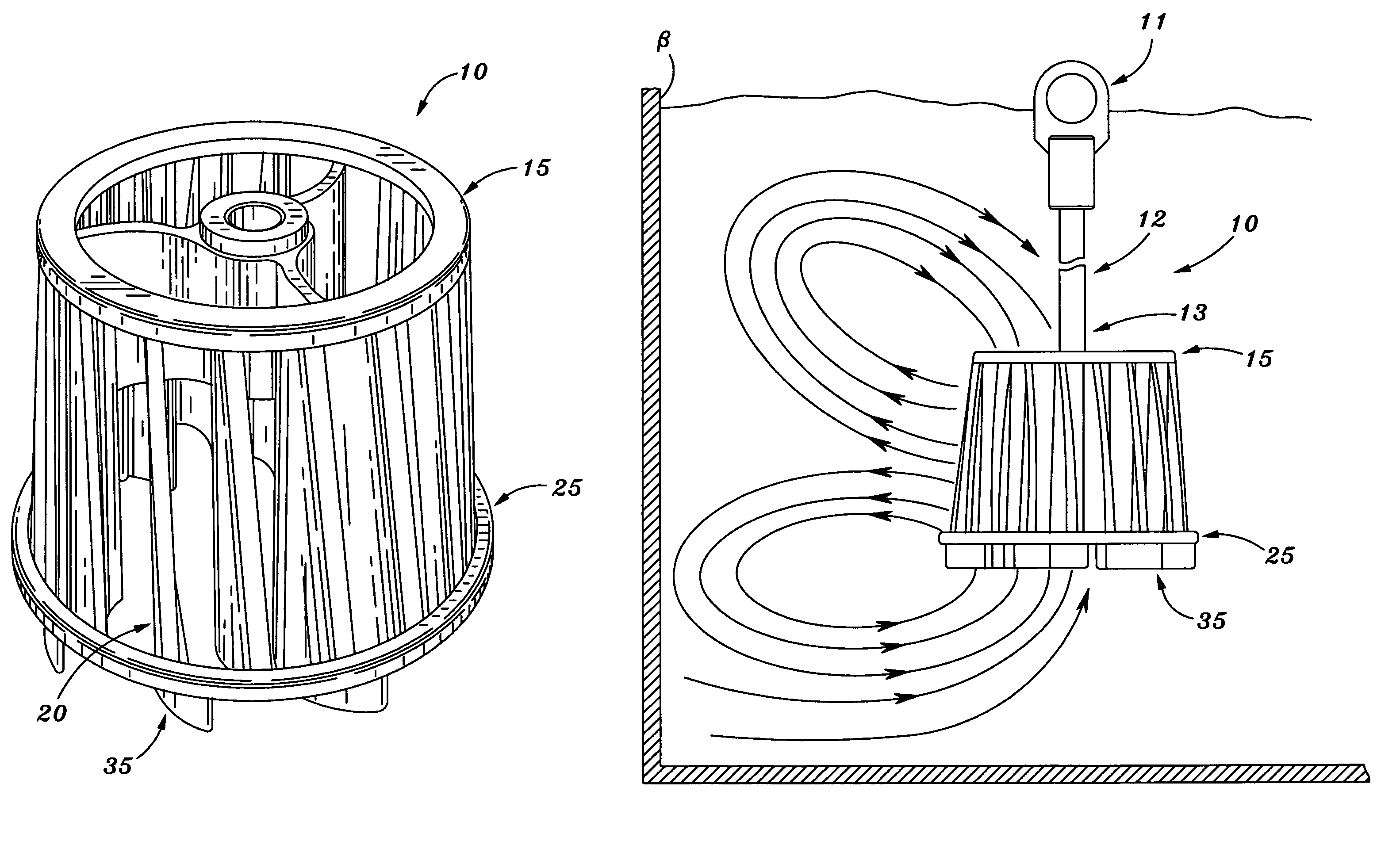
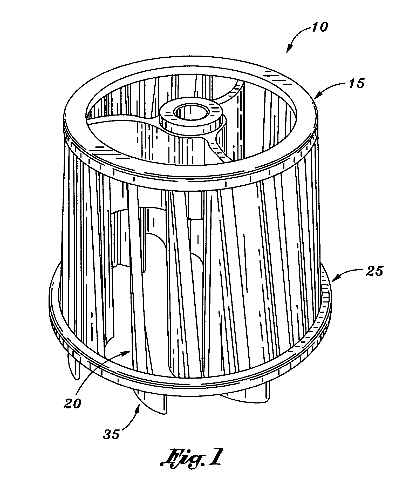
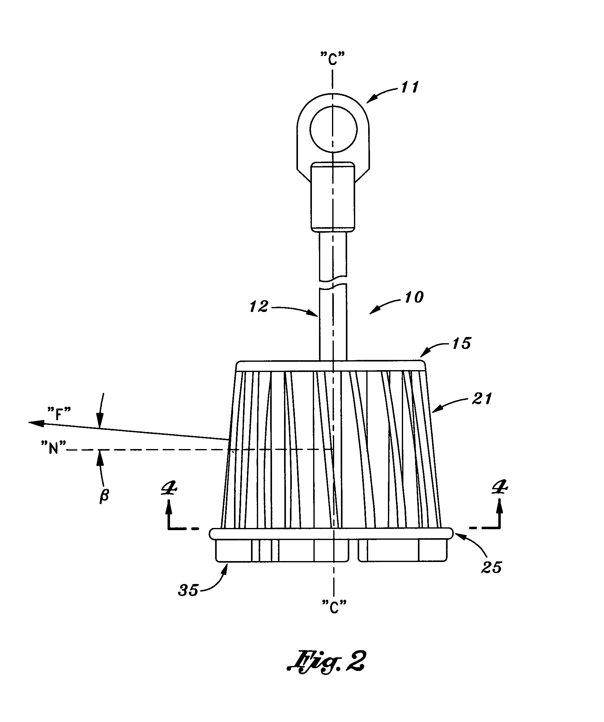
[0029]Referring to FIGS. 1–6, a mixing device according to the present invention is shown generally at 10. Mixing device 10 preferably includes an upper rim 15 and a lower rim 25, each aligned along a common central axis C. A plurality of vanes 20 are positioned between upper rim 15 and lower rim 25 and are attached in fixed relation thereto. In a preferred embodiment, vanes 20, upper rim 15 and a lower rim 25 are integrally constructed of a thermoplastic material, although any appropriate material may be used. Vanes 20 are longitudinally aligned with each other to form a substantially circular shape at their ends corresponding to the circular shape of upper rim 15 and a lower rim 25.

[0030]As shown in FIGS. 3 and 4, each vane 20 is preferably curved, having a convex side 27 and a concave side 29, although such curvature is not necessary. Vanes 20 are preferably orientated in a direction that will allow outward movement of fluid within mixer 10 while in use, shown generally as direct...


PUM


Abstract

A mixing device includes vanes arranged so that the outer edges of the vanes define a frusto-conical surface in order to facilitate improved circulation of the liquid being mixed. Each vane is preferably curved, either lengthwise, widthwise, or both. In one embodiment, the outer edges of the vanes are tapered outward to form the frusto-conical surface. In an alternative embodiment, the inner and outer edges of the vanes are aligned with each other, and the vanes are tilted relative to a central axis to form the frusto-conical surface. The vanes may extend between upper and lower rims having the same or different diameters. Turbines extend between the vanes and shaft for rotating the mixing device. The turbines are arranged to avoid inhibiting entry of liquids through the top and bottom of the mixing device. Feet extend downward from the bottom edge of the mixing device to facilitate mixing of liquids on the bottom of the container. The inner edges of the vanes define a frusto-conical surface in order to prevent clogging of the mixing device.

Description

CROSS-REFERENCE TO RELATED APPLICATION[0001]This application is continuation of U.S. patent application Ser. No. 09 / 928,542, filed Aug. 13, 2001, now abandoned, which application claims the benefit of Provisional Application Ser. No. 60 / 224,702, entitled “Fluid Mixing Device”, filed Aug. 11, 2000, the contents of which are incorporated by reference herein in their entirety.BACKGROUND OF THE INVENTION[0002]1. Field of the Invention[0003]The present invention relates generally to a mixing device for paint and other liquids, and more particularly to mixing device having vanes that form interior and / or exterior frusto-conical surfaces, and feet on the bottom of the mixer, to improve mixing and to prevent clogging.[0004]2. Description of the Related Art[0005]Rotating paint mixers for use with power drills are well known in the art. These devices generally include a shaft that is adapted to be attached to the driving end of the electric drill. The opposite end of the shaft includes an app...

Claims


Application Information

Patent Timeline
IPC IPC(8): B01F27/96B01F25/60
CPCB01F7/00241B01F7/00583B01F7/1625B01F2215/005B01F27/111B01F27/13B01F27/81B01F2101/30
Inventor GRINGER, DONALDCHENG, YUAN FANGSOLED, HOWARD
Owner PPG ARCHITECTURAL FINISHES INC
Why Eureka
Try Eureka