
Sample dispensing apparatus

Active Publication Date: 2008-07-03
HITACHI HIGH-TECH CORP
View PDF2 Cites 4 Cited by
  • Summary
  • Abstract
  • Description
  • Claims
  • Application Information

AI Technical Summary

Benefits of technology

[0011]In view of the problems described above, an object of the present invention is to prevent internal contamination of a dispensing apparatus caused by a sample dripped from a nozzle chip and an abnormal sucking operation caused by a dried and condensed sample within the nozzle chip.
[0014]With the present invention, a dispensing-suspended time during which restart of exchange of child sample containers is waited is measured, and when a prespecified period of time elapses, a nozzle chip set on a current dispensing head is discarded, so that such troubles as dripping of a sample remaining in a nozzle chip, drying and condensing of the sample, and clogging can be prevented. Thus, it is possible to prevent negative effects by the troubles as described above over a result of analysis by an analyzer or internal contamination of a dispensing apparatus.

Problems solved by technology

However, when a jam occurs in the downstream from a dispensing device and a new child sample container to be exchanged with a current one cannot be carried in from a dispensing apparatus, the current one cannot be exchanged with a new one, and the dispensing operation is temporally stopped.
In the state where the dispensing operation is stopped and exchange of a child sample container with a new one cannot be performed, a sample remaining in a nozzle chip drips from the nozzle chip and contaminates the inside of the dispensing apparatus.
When the sample in the nozzle chip is dried, condensed, and solidified, the solidified sample will cause clogging when the operation of sucking the sample is restarted.

Method used


Image

  • Sample dispensing apparatus
  • Sample dispensing apparatus
  • Sample dispensing apparatus

Examples


Embodiment Construction

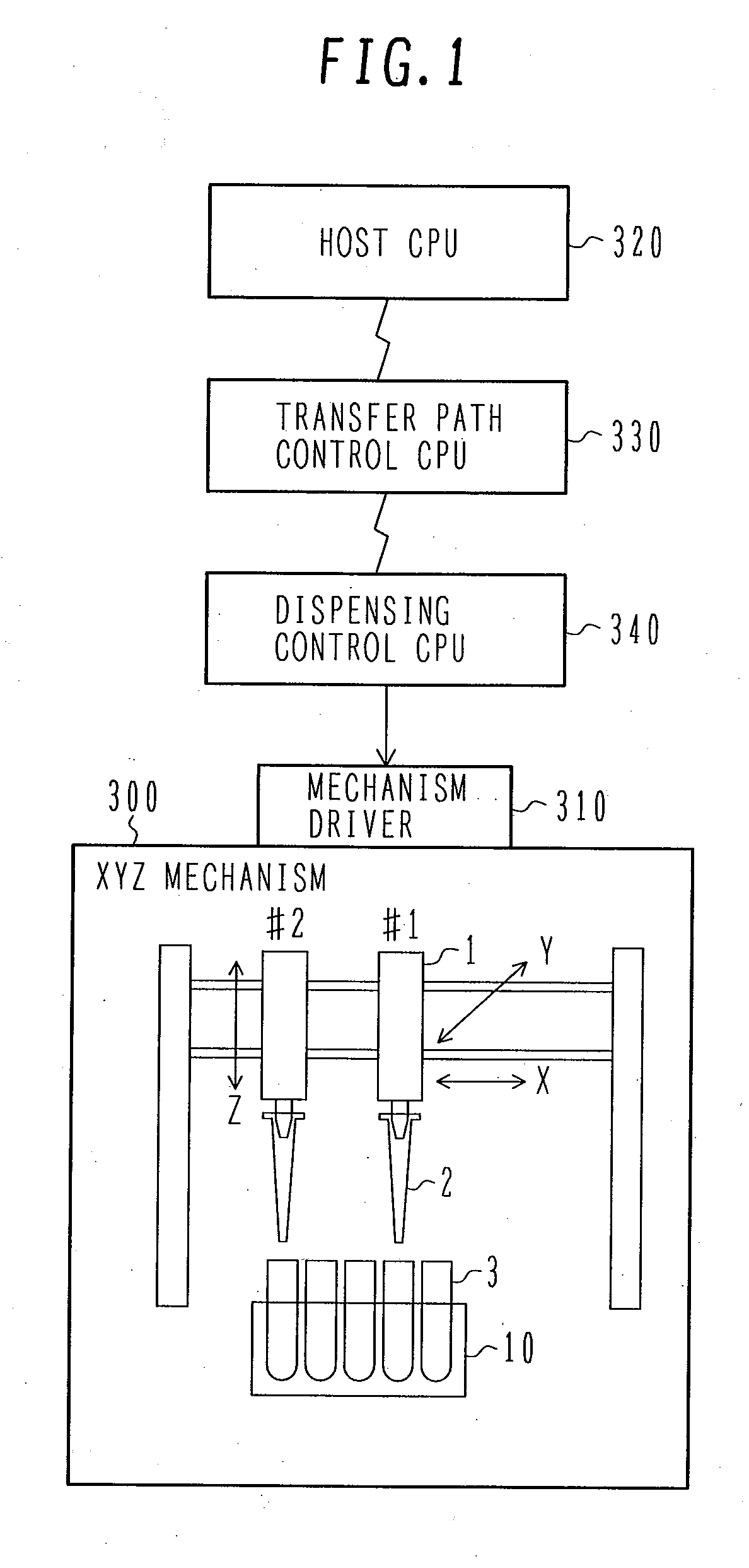
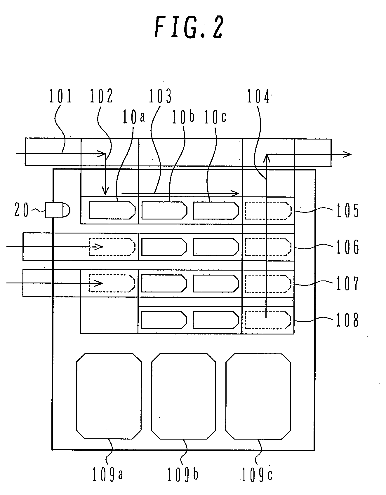
[0018]An embodiment of the present invention is described below with reference to FIG. 1 to FIG. 3.

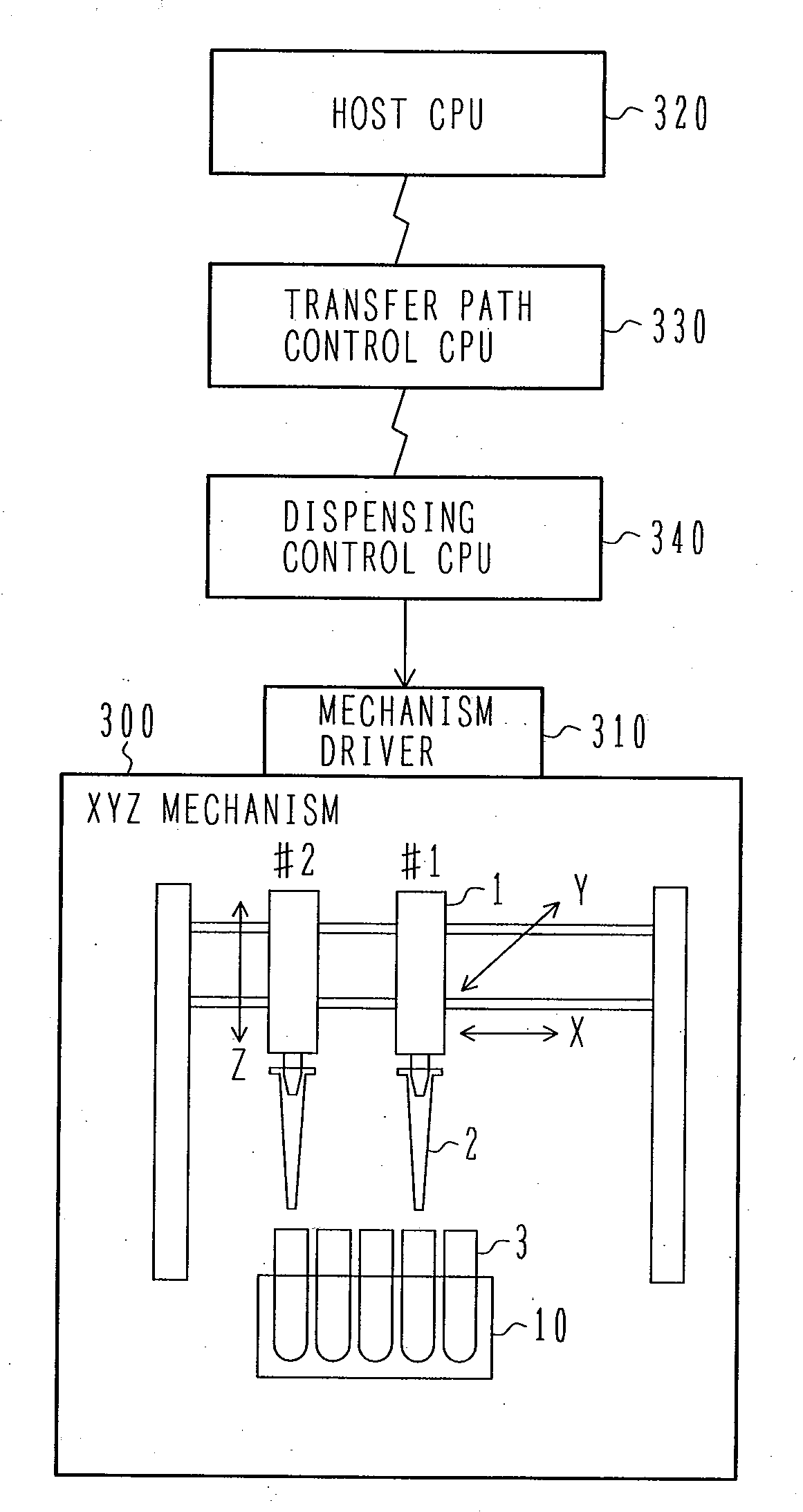
[0019]FIG. 1 is a view illustrating an example of a configuration of a control system according to the present invention.

[0020]A plurality of dispensing heads 1 (#1 and #2 in FIG. 1) are mounted on an XYZ movement mechanism 300 and are used for dispensing a sample such as blood serum or urea.

[0021]A dispensing device includes the XYZ mechanism 300 holding the dispensing head 1 and moving in the vertical direction as well as in the horizontal direction, and a mechanism driver 310 for driving the XYZ mechanism.

[0022]The dispensing head 1 mainly comprises a nozzle base on which a nozzle chip 2 is mounted, a vacuum sucking section for sucking and discharging a sample, a pressure detector for converting a pressure change in sucking or discharging to an electric signal, and a signal processing circuit, and sucks and discharges a sample from a hole provided at a tip of the nozzle chip 2.

[0023...


PUM


Abstract

A sample dispensing apparatus dispenses a sample from a container accommodating a sample such as blood or urea sampled for checking. This sample dispensing apparatus can prevent internal contamination of the apparatus due to dripping of the sample and abnormal sucking operations caused by drainage, condensation and fixing of the sample. The sample dispensing apparatus according to the present invention comprises a dispensing device for dispensing a sucked sample, a dispensing head provided in the dispensing device, and a disposable nozzle chip dismountably set on the dispensing head. In this apparatus, dispensing of a sample to child sample containers is performed exchanging the child sample containers with new ones. When the state, in which dispensing to the child container cannot be carried out, is continued for a prespecified period of time, the nozzle chip is automatically released from the dispensing head.

Description

BACKGROUND OF THE INVENTION[0001]1. Field of the Invention[0002]The present invention relates to a sample dispensing apparatus, and more specifically to a sample dispensing apparatus for dispensing a sample with a disposable nozzle chip, carrying out the dispensed samples to a transfer line and transferring the samples.[0003]2. Description of the Related Art[0004]The sample dispensing apparatus is disclosed, for example, in JP-A-11-304814.[0005]The sample dispensing apparatus is operated as follows: A sample is sucked into a disposable nozzle chip with the use of the nozzle chip for each sample and then discharged a small amount of the sample to the another container to automatically distribute a sample such as blood and urine from a container filled with the sample to another container by the amount required for analysis or examination.[0006]A child sample container into which the sample is dispensed is automatically exchanged with a new one. However, when a jam occurs in the downs...

Claims


Application Information

Patent Timeline
IPC IPC(8): B01L3/02
CPCG01N35/10
Inventor TAKAYA, EIJIKAKUNO, MASAHITOHAGIYA, SATOSHIOIZUMI, JUNICHISUZUKI, NOBUO
Owner HITACHI HIGH-TECH CORP
Learn More