Sprayer

Active Publication Date: 2013-10-01
TERUMO KK
View PDF36 Cites 4 Cited by
  • Summary
  • Abstract
  • Description
  • Claims
  • Application Information

AI Technical Summary

Benefits of technology

[0007]In accordance with the sprayer disclosed here, when a liquid is ejected from the nozzle, gas permeates (flows into) the liquid flow path through a gas permeable film from a gas flow path, and the liquid ejects together with the gas. Then, when the ejection of the liquid is stopped, the residual pressure in the gas flow path causes the gas to flow into the liquid flow path through the gas permeable film. As a result

Problems solved by technology

As a result, clogging occurs in each of the liquid ejection port.
Accordingly, the liquids are also mixed with e

Method used


Image

  • Sprayer
  • Sprayer
  • Sprayer

Examples


Example

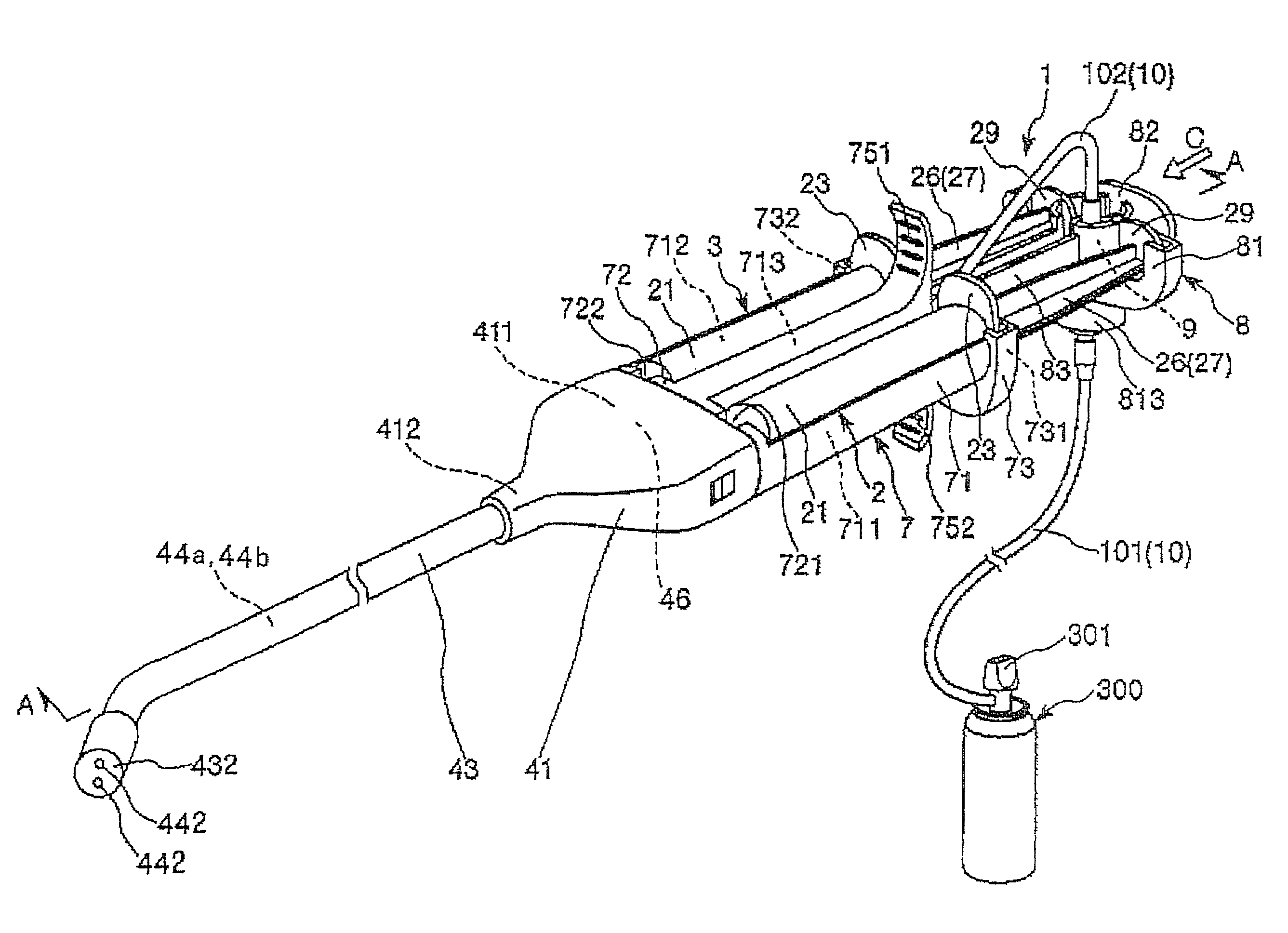
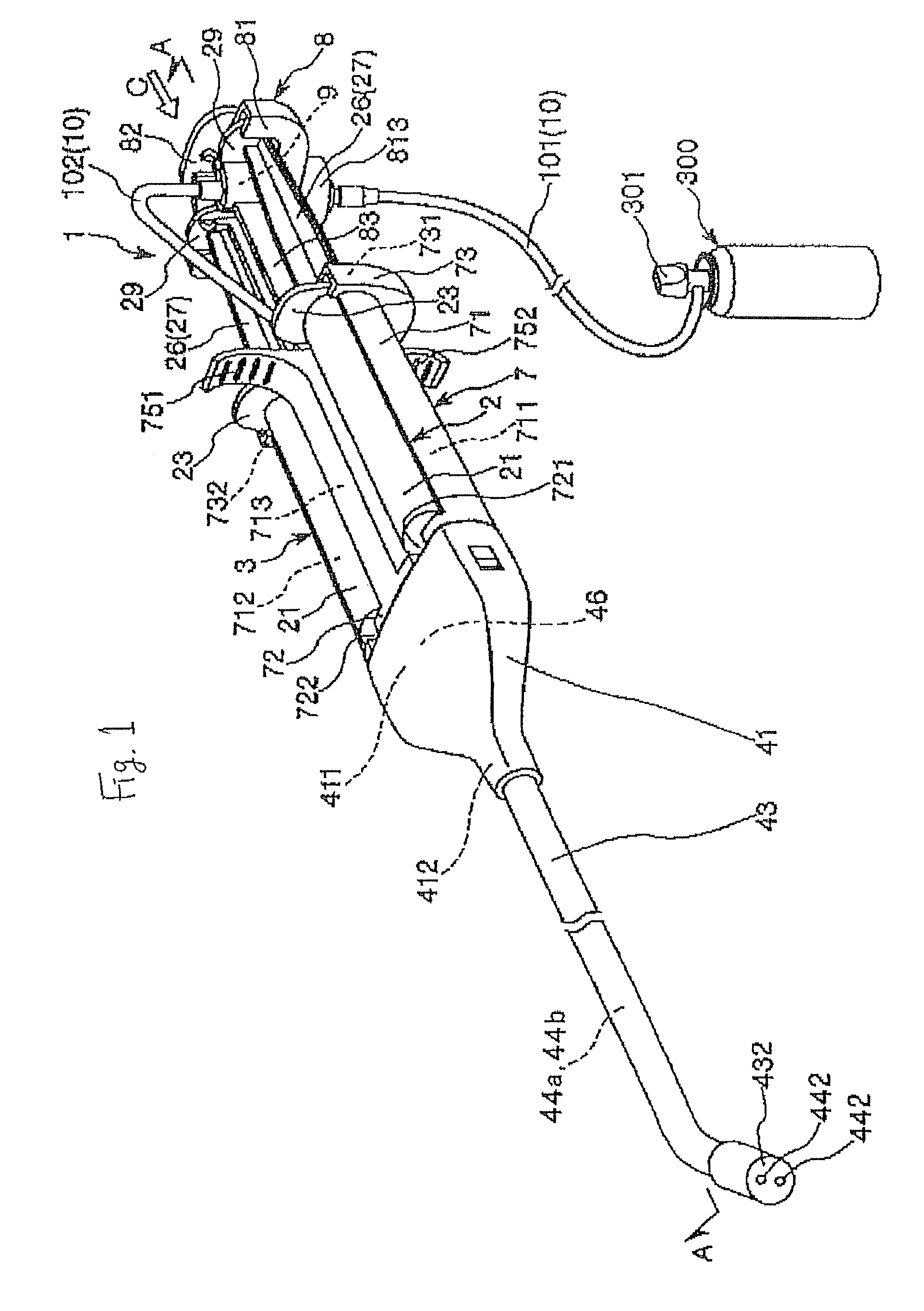
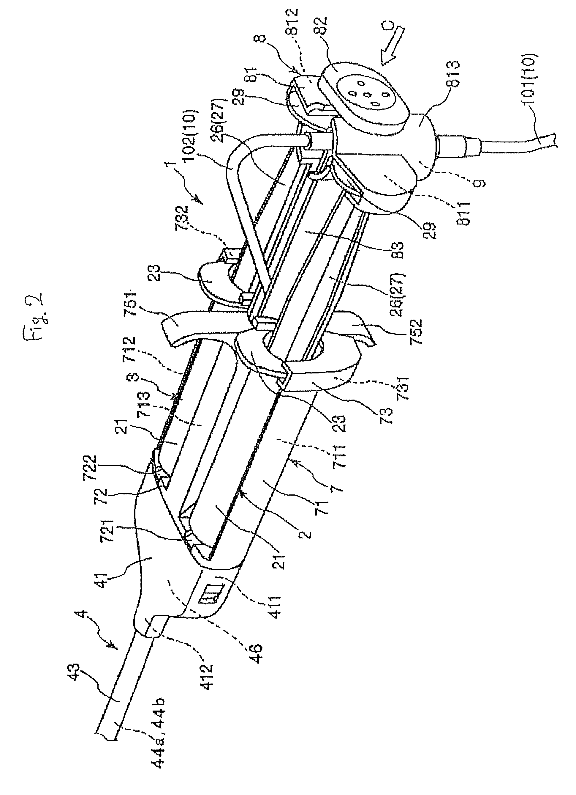
[0036]FIGS. 1-9 illustrate aspects of a sprayer according to a first embodiment. For convenience in description, the left hand side in FIGS. 1, 2 and 5-9 is referred to as the distal end; and the right hand side is referred to as the rear end (proximal end). In FIG. 27, the lower side is referred to as the distal end, and the upper side is referred to as the rear end. Further, in FIGS. 1-4, the upper side is referred to as the top while the lower side is referred to as the bottom.

[0037]The sprayer 1 disclosed here is configured to spray two types of liquids that are different in liquid composition from each other (a first liquid L1 and a second liquid L2), with the liquids being mixed during the spraying as generally illustrated in FIG. 7. As shown in FIGS. 1 and 2, the sprayer 1 is used with a first liquid-containing tube 2 (first syringe), forming a liquid supply means, and a second liquid-containing tube 3 (second syringe) forming a liquid supply means. Referring to FIG. 27, the ...

Example

[0124]The third embodiment of the sprayer disclosed here is the same as the first embodiment, except that the arrangement of the gas permeable films is different.

[0125]The sprayer 1B shown in FIGS. 15 and 16 includes a plurality of gas permeable films 42 set in the first internal tube 44a and the second internal tube 43b. The gas permeable films 42 are arranged intermittently or in spaced apart relation to one another (at equal intervals) along the longitudinal direction of the first internal tube 44a. This description also applies to the second internal tube 44b.

[0126]Each gas permeable film 42 possesses flexibility by appropriately setting, for example, the thickness of the wall part or the constituent material forming the gas permeable film. As shown in FIG. 16, when the gas G is supplied into the external tube 43, the pressure in the external tube 43 increases (an external force is applied), so that warp is caused in the central part in the longitudinal direction of each gas pe...

Example

[0142]This embodiment is the same as the fourth embodiment, except that the setting position of each gas permeable film 42 is different.

[0143]In the sprayer 1D shown in FIG. 21, respective gas permeable films 42 are set in the first internal tube 44a and the second internal tube 44b, respectively. The respective gas permeable films 42 are set in the vicinity of the merge part 52.

[0144]With the sprayer 1D thus configured, the operation of the operation part 8, upon stopping the ejection of the first liquid L1 and the second liquid L2, the gas G which has flowed through respective gas permeable films 42 can blow away not only the liquid mixture in the merge part 52 but also the first liquid L1 in the first internal tube 44a (gas permeable film 42) and the second liquid L2 in the second internal tube 44b (gas permeable film 42) from the ejection port 524. This can help prevent the first liquid L1 and the second liquid L2 from remaining in the ejection port 524, and causing clogging in ...


PUM


Abstract

A sprayer which inhibits or prevents clogging from occurring in a nozzle when a liquid is ejected from the nozzle includes a nozzle having a first internal tube through which a first liquid passes, and a second internal tube through which a second liquid passes. An external tube is provided in which the first internal tube and the second internal tube are positioned so that the gas passes therebetween. In the sprayer, each distal end part of the first internal tube and the second internal tube includes a gas permeable film impermeable to each liquid, and permeable to the gas.

Description

TECHNOLOGICAL FIELD[0001]The present invention generally relates to a device for delivering a liquid material. More specifically, the invention pertains to a sprayer having useful application in the medical field for spraying a liquid at a body region.BACKGROUND DISCUSSION[0002]Conventionally, there is known a method in which two or more liquids are mixed and ejected to an affected part or the like of a living body to form, for example, an anti-adhesive material, a biological tissue adhesive, etc. Thus, developmental efforts in the area of sprayers have been made.[0003]Such a sprayer is configured to feed components which coagulate upon mixing, such as a thrombin-containing solution and a fibrinogen-containing solution, in a mutually separated manner to the vicinity of the affected part, and to spray them while mixing at the affected part. One conventional sprayer includes two syringes respectively containing different types of liquids, and a nozzle for mixing the liquids from respe...

Claims


Application Information

Patent Timeline
IPC IPC(8): A61B19/00
CPCB01F5/0262B01F13/0023B01F13/0222B01F13/0227B01F15/0087B05B7/1281B05B7/2467B05B7/2472A61B17/00491A61M11/00A61M11/006B05B7/0408B05B7/0433B05B7/0441B05B7/0491B05B7/0846B05C17/00553B05C17/01B01F25/231B01F33/50112B01F33/404B01F33/403B01F35/522
Inventor HAYAKAWA, KOICHI
Owner TERUMO KK
Why Eureka
Try Eureka