Quick-release tube clamp for modular lower limb prosthetic systems and method thereof

a technology of modular lower limb prosthesis and clamping tube, which is applied in the direction of rod connections, prosthesis, couplings, etc., can solve the problems of substantial inconvenience for users and achieve the effect of reducing the width of the formed slo

Inactive Publication Date: 2005-12-06
AMPU CLAMP
View PDF42 Cites 54 Cited by
  • Summary
  • Abstract
  • Description
  • Claims
  • Application Information

AI Technical Summary

Benefits of technology

[0019]The clamp portion is located near the lower end of the tubular portion firmly locks the tubular portion around the tubular pylon when the tubular pylon is inserted into the tubular position and provides a releasing position for removal of the tubular pylon. The clamp portion includes a pair of opposing tabs located on opposing sides of the formed slot and a handle. The handle has a cam at one end and is curved to follow the shape of the tubular portion. When the handle is moved into the locking position, the cam operates on the pair of opposing tabs to lock the tubular portion around the inserted tubular pylon by reducing the width of the formed slot.

Problems solved by technology

This presents a substantial inconvenience to the user.

Method used


Image

  • Quick-release tube clamp for modular lower limb prosthetic systems and method thereof
  • Quick-release tube clamp for modular lower limb prosthetic systems and method thereof
  • Quick-release tube clamp for modular lower limb prosthetic systems and method thereof

Examples


Embodiment Construction

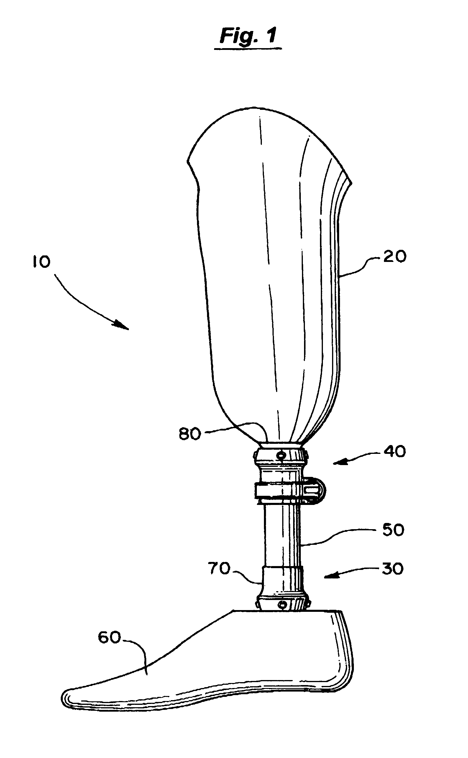
[0026]In FIG. 1, a modular lower limb prosthetic system 10 is shown to include a conventional socket 20 and a conventional pylon / foot component 30. The quick-release tube clamp 40 of the present invention is shown firmly connecting the pylon / foot component 30 to the socket 20.

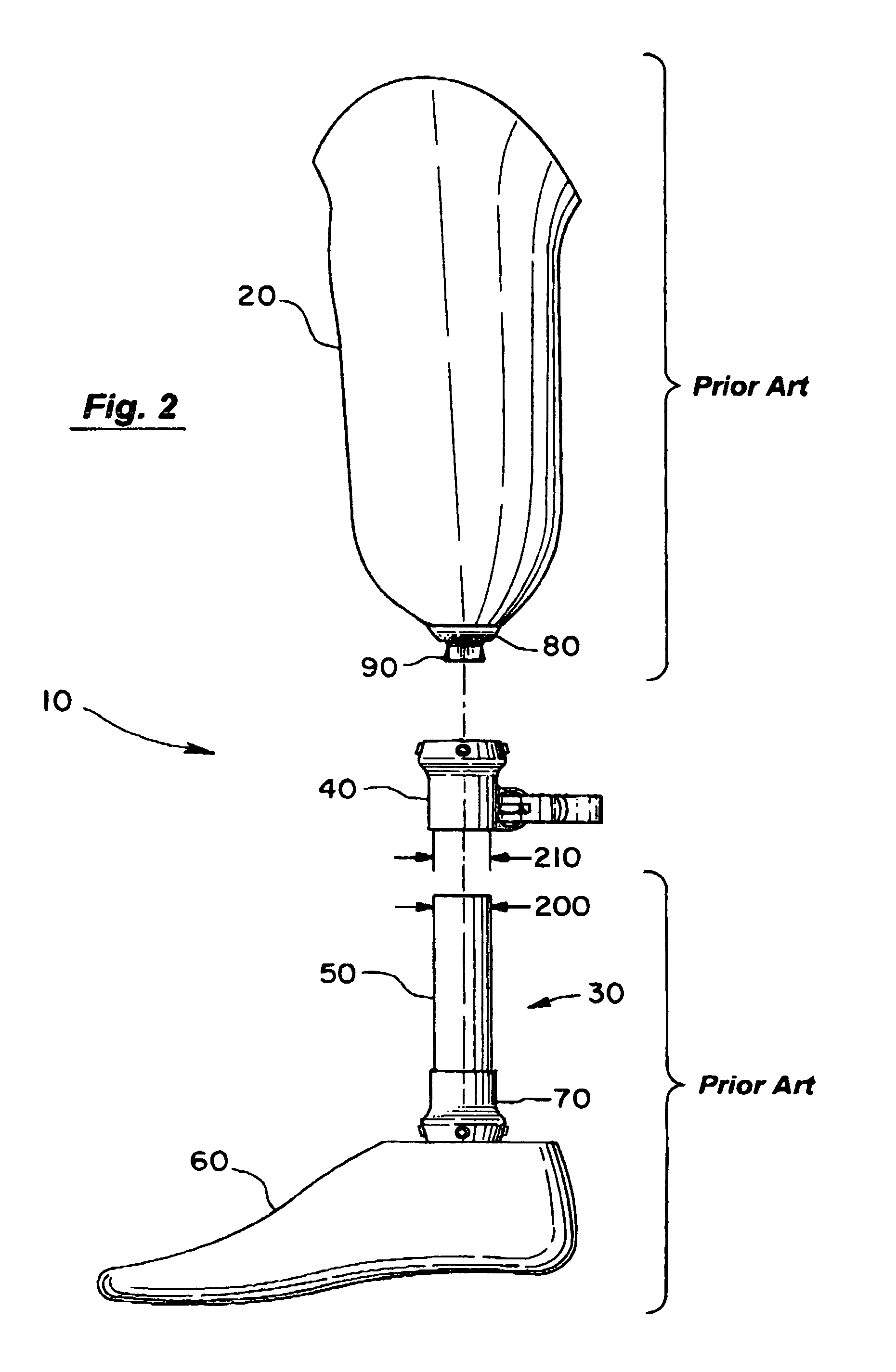
[0027]In FIG. 2, the quick-release tube clamp 40 of the present invention is shown released from the socket 20 and released from the pylon / foot component 30. The conventional pylon / foot component 30 also has a conventional tubular pylon 50 and a conventional prosthetic foot 60. The tubular pylon 50 is connected with a conventional connector 70 to the prosthetic foot 60. It is to be expressly understood that the pylon / foot component 30 is conventional, as is the tubular pylon 50, the prosthetic foot 60, and the connector 70. Connector 70 can be a complex connector or simply using epoxy to glue the tubular pylon 50 to the foot 60. The present invention is not limited to the pylon / foot component 30 and any of a nu...


PUM


Abstract

A quick-release tube clamp and method therefor for locking and releasing a prosthetic pylon / foot component from the socket. The quick-release tube clamp includes a tubular portion, an annular socket portion, and a clamp portion. The tubular portion has a formed slot along a longitudinal length of the tubular portion. The tubular portion forms a cylindrical opening with an inner diameter slightly larger than the outer diameter of the tubular pylon. The annular socket at the upper end of the tubular portion attaches to the socket of the modular lower limb prosthetic system. The clamp portion is located near the lower end of the tubular portion and firmly locks the tubular portion around the tubular pylon when the tubular pylon is inserted into the tubular position and provides a releasing position for removal of the tubular pylon.

Description

BACKGROUND OF THE INVENTION[0001]1. Field of the Invention[0002]The invention relates to a mechanism for releasing a prosthetic pylon / foot component from a lower limb prosthetic socket and, more particularly, to providing a quick-release for such a mechanism and method therefor.[0003]2. Discussion of the Background[0004]With the introduction of modular prosthetics in the mid-1990's, a number of conventional mechanisms have been designed to connect and to release a prosthetic pylon / foot component from the prosthetic socket of a user. In the lower limb prosthesis industry, a conventional link-plate is rigidly attached to the base of the socket, the link-plate typically has a downwardly extending pyramidal boss. A connector with an annular socket usually having four set screws couples to the pyramidal boss. The four set screws are adjusted and tightened, usually by a trained professional, to provide proper fitting for the prosthetic pylon / foot component. This is found, for example, in ...

Claims


Application Information

Patent Timeline
Patent Type & Authority Patents(United States)
IPC IPC(8): A61F2/00A61F2/60A61F2/62A61F2/76A61F2/80F16B2/02F16B2/14
CPCA61F2/76A61F2/60A61F2/80A61F2002/30505Y10T403/7071A61F2220/0025Y10S403/04Y10T403/5793A61F2002/607
Inventor BENSON, RICHARD MYRLE
Owner AMPU CLAMP
Why Eureka
Try Eureka