Maximum time interval error test signal generating apparatus not affected by low-pass measuring filter

a signal generating apparatus and maximum time interval technology, applied in the field of mtie test signal generating apparatus, can solve problems such as increased detection errors and unstable signal operation

Inactive Publication Date: 2005-12-06
ANRITSU CORP
View PDF7 Cites 8 Cited by
  • Summary
  • Abstract
  • Description
  • Claims
  • Application Information

AI Technical Summary

Benefits of technology

[0055]The object of the present invention is to solve the above-described conventional problems and then provide an MTIE test signal generating apparatus capable of detecting an MTIE characteristic by means of an MTI

Problems solved by technology

On the other hand, if the measuring object 1 cannot follow changes in the phase of the test signal Q,

Method used


Image

  • Maximum time interval error test signal generating apparatus not affected by low-pass measuring filter
  • Maximum time interval error test signal generating apparatus not affected by low-pass measuring filter
  • Maximum time interval error test signal generating apparatus not affected by low-pass measuring filter

Examples


first embodiment

(First Embodiment)

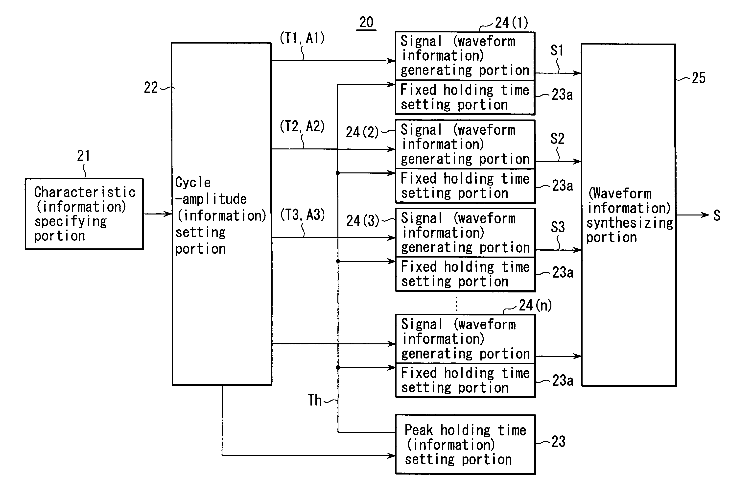
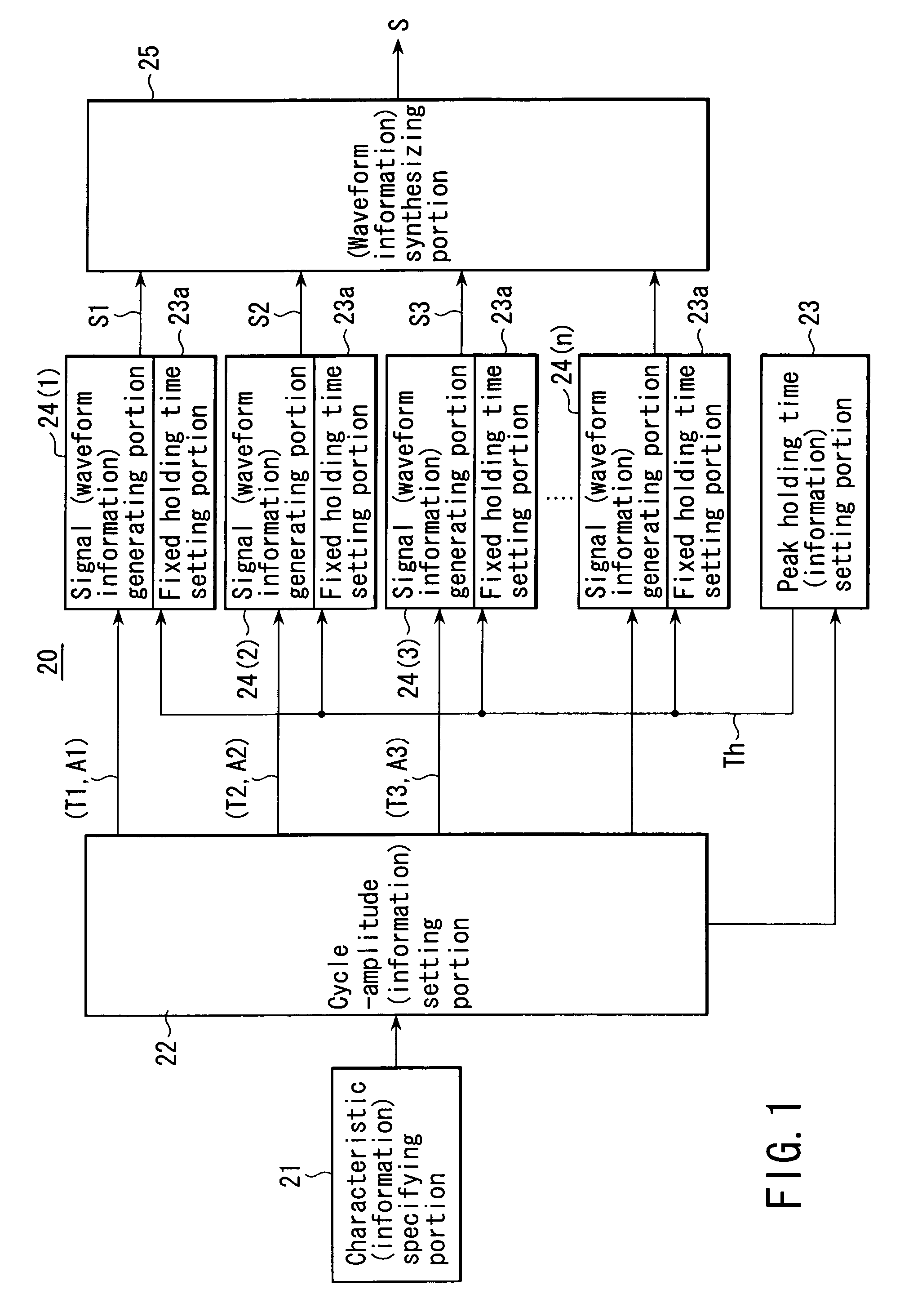
[0104]FIG. 1 shows a block structure of an MTIE test signal generating apparatus 20 according to the first embodiment of the present invention.

[0105]This MTIE test signal generating apparatus 20 comprises a characteristic specifying portion 21, a cycle-amplitude setting portion 22, a holding time setting portion (peak holding time setting portion) 23, plural signal generating portions 24(1), 24(2), . . . 24(n) and a synthesizing portion 25.

[0106]The characteristic specifying portion 21 specifies a desired MTIE characteristic from plural MTIE characteristics including plural specific points. User inputs data about observation time and MTIE value of each specific point of the desired MTIE characteristic through an operating portion or the like (not shown) of the characteristic specifying portion 21 or selects and specifies one of the plural MTIE characteristics based on data about the specific points stored in a memory in advance.

[0107]The cycle-amplitude setting por...

second embodiment

(Second Embodiment)

[0165]FIG. 4 is a block diagram showing the second embodiment of the MTIE test signal generating apparatus of the present invention.

[0166]Like reference numerals are attached to the same components in FIG. 4 as those of the MTIE test signal generating apparatus 20 of the first embodiment shown in FIG. 1 and description thereof is omitted.

[0167]As regards the MTIE test signal generating apparatus 20 of the first embodiment, a case where the high-cut frequency of the LPF 18a for extracting a wander of the wander measuring unit 18 has been described.

[0168]However, the MTIE test signal generating apparatus 20 of the second embodiment is applied for a case where the high-cut frequency fc of the LPF 18a for extracting a wander of the wander measuring unit 18a is variable arbitrarily.

[0169]As shown in FIG. 4, the MTIE test signal generating apparatus 20 of the second embodiment is provided with a high-cut frequency setting portion 26 which sets a high-cut frequency corre...


PUM


Abstract

An MTIE test signal generating apparatus generates a predetermined MTIE test signal. An MTIE measuring unit includes a low-pass measuring filter having a predetermined high-cut characteristic. A cycle-amplitude setting portion sets a cycle corresponding to an observation time of each of desired plural specific points for a predetermined MTIE characteristic and an amplitude corresponding to a difference in the MTIE value between adjacent specific points. Plural signal generating portions generate plural signals each having the cycle and the amplitude having repetitive waveforms and then outputting to each of the desired plural specific points. A holding time setting portion sets a holding time for holding the upper and lower limit values of the repetitive waveforms over the predetermined time so that a signal cycle having at least the shortest cycle of the plural signals is longer than a predetermined time corresponding to the predetermined high-cut characteristic of the low-pass measuring filter.

Description

CROSS-REFERENCE TO RELATED APPLICATIONS[0001]This application is based upon and claims the benefit of priority from the prior Japanese Patent Application No. 2002-303552, filed Oct. 17, 2002, the entire contents of which are incorporated herein by reference.BACKGROUND OF THE INVENTION[0002]1. Field of the Invention[0003]The present invention relates to an MTIE test signal generating apparatus for generating a phase modulation signal necessary for obtaining a desired wander in maximum time interval error (MTIE) characteristic and more particularly to an MTIE test signal generating apparatus which adopts technology for prohibiting generation of a measurement error due to the influence of a high-cut filter for extracting a wander in an MTIE measuring apparatus.[0004]2. Description of the Related Art[0005]Upon testing the characteristics of a synchronous digital hierarchy (SDH) communication system on changes in phase, a test signal specified by an evaluation amount called maximum time ...

Claims


Application Information

Patent Timeline
IPC IPC(8): H04L27/18H04B7/26H04J3/06H04J3/14H04L1/20H04L1/24H04L25/02
CPCH04J3/14H04L1/205H04L1/24
Inventor MOCHIZUKI, KENSUGIYAMA, OSAMU
Owner ANRITSU CORP
Why Eureka
Try Eureka