Computer system with improved data capture system

a data capture system and computer system technology, applied in the field of computer systems, can solve the problems of inability to guarantee the reliability of the operation system, the restrictions of certain communication paths,

Inactive Publication Date: 2005-12-06
DELL PROD LP +1
View PDF9 Cites 11 Cited by
  • Summary
  • Abstract
  • Description
  • Claims
  • Application Information

AI Technical Summary

Benefits of technology

[0013]Other technical advantages of the present disclosure will be readily apparent to one skilled in the art from the following figures, descriptions, an

Problems solved by technology

In addition, the respective operating system might have restrictions with respect to certain communication paths in particular in system crash situations.
Even so this architecture is satisfactory during n

Method used


Image

  • Computer system with improved data capture system
  • Computer system with improved data capture system
  • Computer system with improved data capture system

Examples


Embodiment Construction

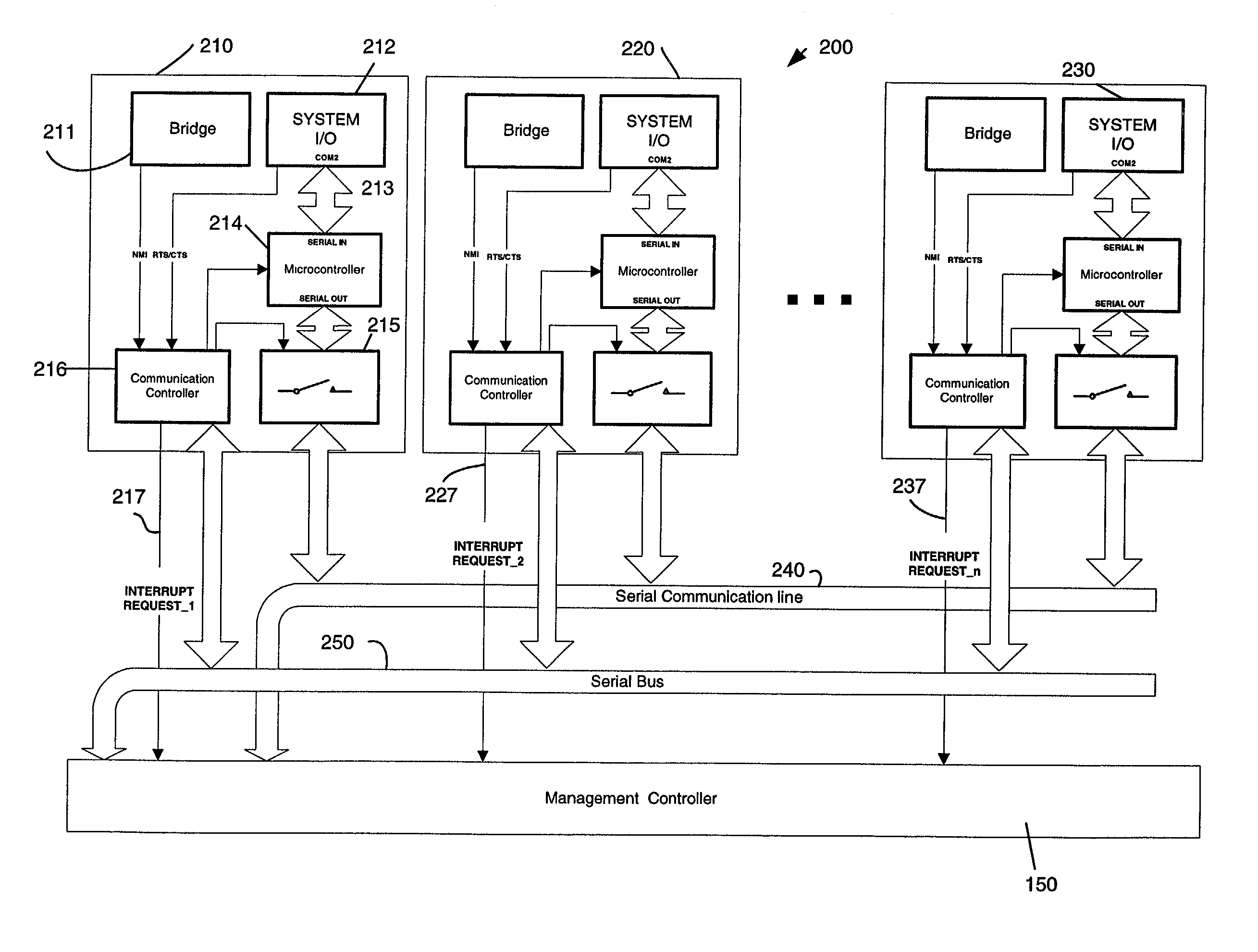
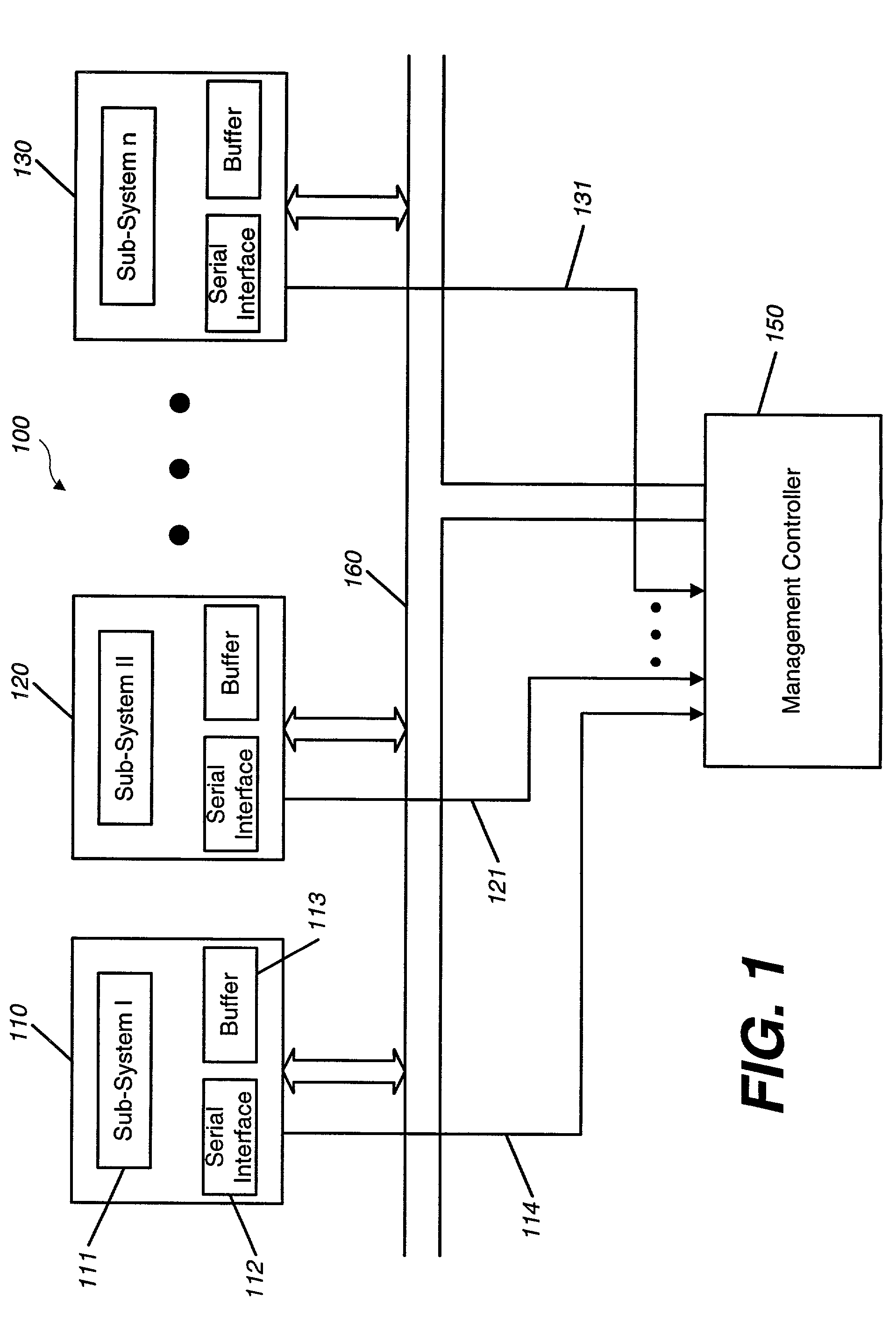
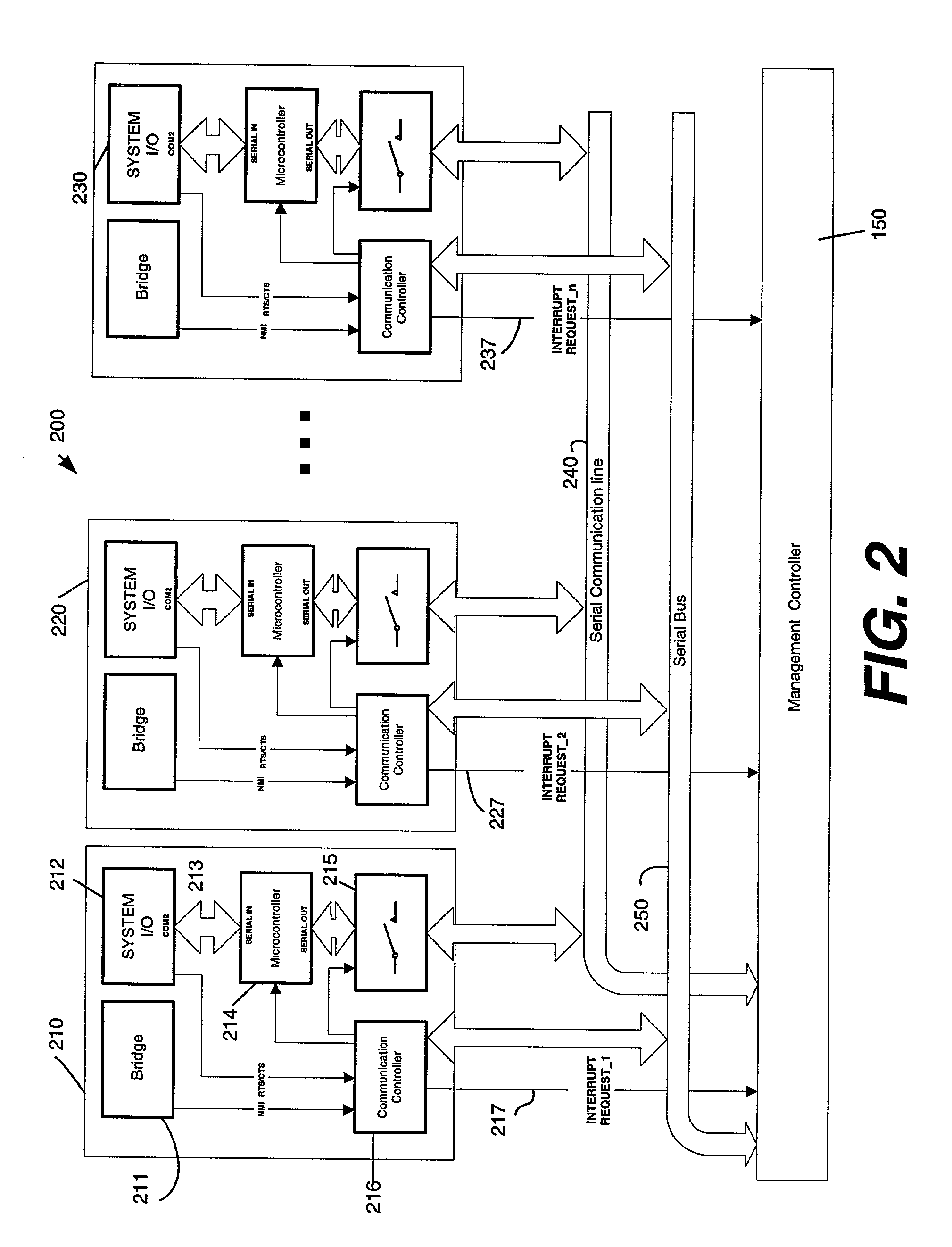
[0020]Turning to the drawings, exemplary embodiments of the present application will now be described. FIG. 1 shows a block diagram of a computer server system 100. Such a system comprises a plurality of sub-systems 110, 120, . . . 130. Each sub-system 110, 120, . . . 130 is an independent computer system, such as a personal computer or a single server. Usually only the motherboards of these computers or servers are used and placed into a rack or tower system. Every sub-system 110, 120, . . . 130 comprises the respective components 111, such as a central processing unit, memory, peripheral interfaces, etc. Usually only one keyboard, mouse and monitor (not shown) are coupled with a keyboard-mouse-monitor managing unit (KVM, not shown) which selectively couples the KVM with one of the sub-systems.

[0021]In FIG. 1 a serial interface is indicated by numeral 112. This serial interface 112 is one of the peripherals which are on the motherboard of a computer system and is usually a standard...


PUM


Abstract

A computer system has a plurality of sub-systems each comprising a serial interface and a buffer device coupled with the serial interface for buffering crash data sent by the serial interface having an external serial output. The system further comprises a management controller coupled with the external serial output of the buffer device to retrieve data buffered during a crash.

Description

FIELD OF THE INVENTION[0001]The present invention relates to a computer system, including a plurality of independent sub-systems, a control sub-system and an improved mechanism for handling a crash on a sub-system.BACKGROUND OF THE INVENTION[0002]Today's computer systems, in particular server systems, comprise often a plurality of sub-systems. Each sub-system can be an independent computer system running its own operating system. For example, a sub-system can comprise a multiple processor architecture running a WINDOWS® operating system. These sub-systems can thus be fully operational computer systems, for example, personal computers or servers which could be coupled with a keyboard, mouse, monitor, etc. A plurality of those sub-systems can be linked and coordinated through a specific dedicated management bus system which is coupled to an embedded server management controller. To this end, each sub-system comprises a so called bridge to couple with the dedicated bus system. As such ...

Claims


Application Information

Patent Timeline
IPC IPC(8): G06F11/00G06F11/07G06F13/00
CPCG06F11/0709G06F11/0778
Inventor MASUYAMA, JINSAKUKHATRI, MUKUND P.
Owner DELL PROD LP
Why Eureka
Try Eureka