Dock leveler assembly with adjustable automatic release

a leveler and automatic release technology, applied in the direction of bridges, loading/unloading, construction, etc., can solve the problems of affecting the operation of the leveler, the effect of disabling the automatic release function or premature automatic release, and the overall length

Inactive Publication Date: 2005-12-13
MULTI FAB PRODS
View PDF19 Cites 9 Cited by
  • Summary
  • Abstract
  • Description
  • Claims
  • Application Information

AI Technical Summary

Benefits of technology

[0004]It is an object of the present invention to provide an improved automatic release function in a holddown mechanism incorporated in a dock leveler assembly. It is a further object of the invention to provide an automatic release mechanism which is capable of being adjusted so as to accommodate manufacturing tolerances or other variations in components incorporated in the automatic release mechanism. Yet another object of the invention is to provide such an automatic release mechanism which functions in a manner similar to prior art automatic release mechanisms. Yet another object of the invention is to provide such an automatic release mechanism which can be calibrated during manufacture and thereafter retrofitted into an existing dock leveler assembly. A still further object of the invention is to provide a method of calibrating or adjusting an automatic release mechanism so as to provide consistent and reliable operation, either during original manufacture of the dock leveler or when retrofitting an existing dock leveler with a replacement holddown assembly.
[0005]The present invention features an automatic release mechanism for a dock leveler assembly as described above. The dock leveler assembly includes a release member movably interconnected with one of the first and second members of the holddown mechanism, for movement between an inoperative position for maintaining the releasable engagement arrangement in an engaged position to prevent movement between the first and second members, and an operative position for moving the releasable engagement arrangement to a disengaged position for allowing movement between the first and second members. The automatic release mechanism of the present invention includes an adjustable actuator member that defines a first end interconnected with one of the first and second members, and a second end interconnected with the release member. The effective length of the actuator member between the first and second ends is adjustable, which enables variation in the inoperative position of the release member. This adjustability in the inoperative position of the release member functions to control the degree of movement of the release member that is required for moving the release member to the operative position, in which the release member moves the releasable engagement arrangement to the disengaged position for allowing movement between the first and second members of the holddown mechanism, and thereby upward movement of the ramp when an upward force is applied to the ramp.
[0006]The release member is pivotable between the operative and inoperative positions, and the second end of the adjustable actuator member is interconnected with the release member at a location offset from the pivot axis about which the release member is pivotable. When the ramp member is in a lowered position, application of an upward force above a predetermined threshold functions to apply tension to the actuator member so as to cause the actuator member to pivot the release member from the inoperative position to the operative position, so as to disengage the releasable engagement arrangement and to allow movement between the first and second members of the holddown assembly, and thereby movement of the ramp member away from the lowered position partially toward the raised position. When the applied upward force falls below the predetermined threshold, the release member returns to the inoperative position to allow engagement of the releasable engagement arrangement so as to maintain the relative position of the first and second members of the holddown mechanism.

Problems solved by technology

While a fixed length chain of this type is capable of providing satisfactory operation of an automatic release mechanism, it has been found that, in practice, this type of automatic release actuator provides unpredictable and inconsistent performance, primarily due to the large number of high tolerance components (i.e. components that do not have closely controlled tolerances) incorporated in the release mechanism and the chain and the hardware used to mount the chain.
Such lack of close tolerances can significantly affect the overall length of the actuator, which can result in the effective disablement of the automatic release function or providing premature automatic release.

Method used


Image

  • Dock leveler assembly with adjustable automatic release
  • Dock leveler assembly with adjustable automatic release
  • Dock leveler assembly with adjustable automatic release

Examples


Embodiment Construction

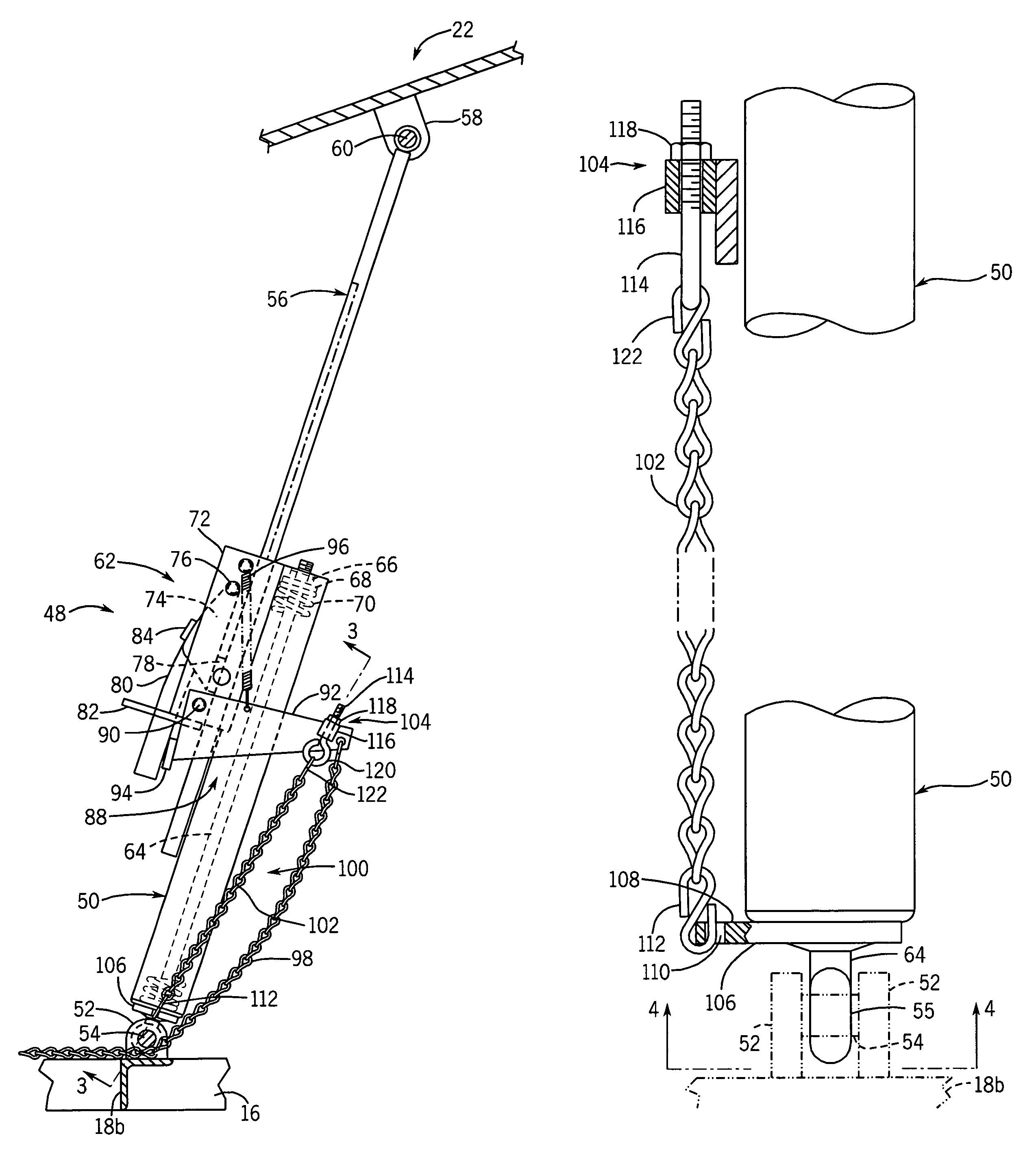
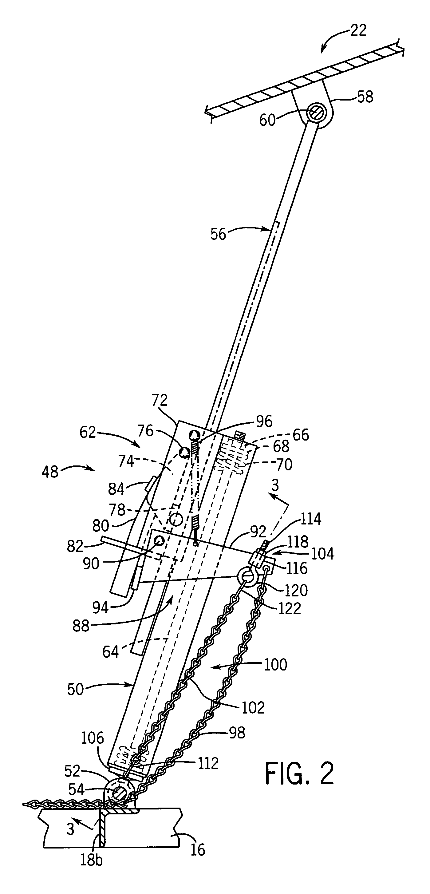
[0018]The adjustable automatic release feature of the present invention is adapted to be used with any type of dock leveler having a holddown mechanism that maintains the ramp of the dock leveler in a lowered position against an upward bias that tends to raise the ramp. The drawings and the following detailed description illustrate the adjustable automatic release feature employed in connection with a dock leveler having a certain illustrative construction, and it is understood that the adjustable automatic release feature may be used in connection with various types of dock leveler assemblies that vary from the specific construction as shown and described.

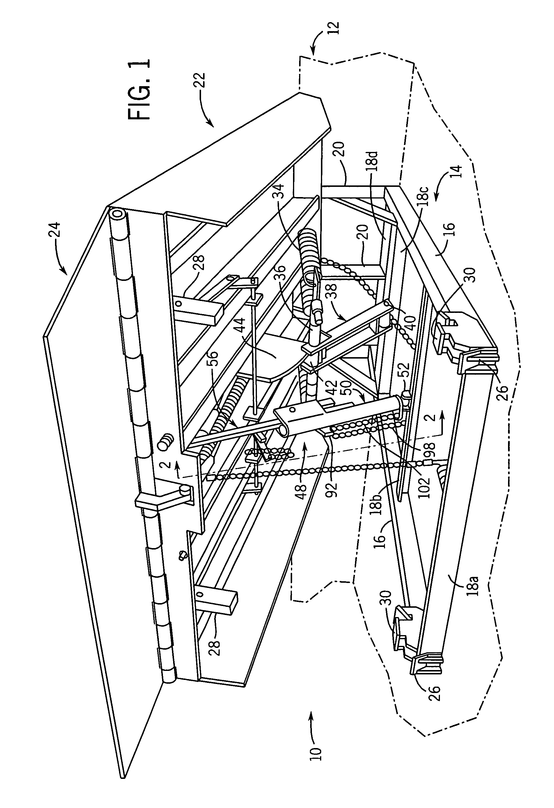
[0019]As shown in FIG. 1, a dock leveler assembly 10 is mounted to a loading dock 12, in a manner as is known. Dock leveler assembly 10 includes a frame or base 14 secured within a loading dock recess, e.g. to the front and back of the recess. Base 14 includes a pair of spaced side members 16 and a series of transverse members 18a...


PUM


Abstract

A dock leveler assembly includes a base and a ramp that is pivotably movable under the influence of a biasing arrangement to a raised position. The ramp is lowered into engagement with a truck bed, preferably via a lip connected to the outer end of the ramp, and a holddown assembly maintains the ramp in a lowered position during loading and unloading of the truck bed against the force of a biasing arrangement that urges the ramp toward a raised position. The holddown assembly includes an extendible and retractable mechanism which is selectively fixed in position to maintain the ramp in a desired position. A “float” apparatus using a compression spring accommodates a certain amount of vertical movement of the ramp as the truck bed moves up and down during loading and unloading. A release arrangement enables the holddown assembly to be extended and retracted, and includes an automatic actuating arrangement that allows the mechanism to be extended upon application of a selected upward force to the ramp when the ramp is in a lowered position. The automatic actuating arrangement includes a flexible member such as a chain, and an adjustment arrangement for adjusting the inoperative position of the release member so as to control the degree of movement of the release member that is required in order to move the release member to the operative position from the inoperative position. The adjustment arrangement may be in the form of a threaded connection between one end of the actuating member and the release member, for selectively varying the inoperative position of the release member. The purpose of the adjustment is to control the amount of upward force that is required to actuate the release member, in order to avoid premature release and to avoid damage that can occur if the release does not occur until after an excessive upward force is applied.

Description

BACKGROUND AND SUMMARY OF THE INVENTION[0001]This invention related to a dock leveler mechanism including an upwardly biased ramp that is pivotably interconnected with a base for movement between raised and lowered positions, and more particularly to an automatic release feature for a holddown mechanism that selectively maintains the ramp in a lowered position and enables upward movement of the ramp in response to application of an upward force on the ramp when the ramp is in a lowered position.[0002]A dock leveler assembly typically includes a base mounted to a loading dock or the like, and a ramp pivotably mounted to the base for movement between raised and lowered positions. A biasing arrangement, such as a spring arrangement, is interposed between the ramp and the base for biasing the ramp upwardly toward a raised position. A holddown mechanism is interposed between the base and the ramp, for selectively maintaining the ramp in a lowered position, such as when the outer end of t...

Claims


Application Information

Patent Timeline
Patent Type & Authority Patents(United States)
IPC IPC(8): B65G69/28E01D1/00
CPCB65G69/2835B65G69/2841B65G69/2876
Inventor MAYER, WILLIAM B.CINEALIS, THOMAS A.HINTZE, DAVID C.
Owner MULTI FAB PRODS
Why Eureka
Try Eureka