Socket assembly that can be mounted and detached quickly

a fast and convenient technology, applied in the field of socket assemblies, can solve the problems of increasing the cost of fabrication, inconvenience to users, and complicated manufacturing procedures, and achieve the effect of mounting and disassembling easily and quickly

Inactive Publication Date: 2005-12-13
HUANG JUNG CHIH
View PDF14 Cites 66 Cited by
  • Summary
  • Abstract
  • Description
  • Claims
  • Application Information

AI Technical Summary

Benefits of technology

[0006]The primary objective of the present invention is to provide a socket assembly that can be mounted and detached easily and rapidly.
[0007]Another objective of the present invention is to provide a socket assembly that can prevent the screwdriver head from being falling down when the screwdriver head is removed from the socket assembly.
[0008]A further objective of the present invention is to provide a socket assembly, wherein the screwdriver head is locked by the locking member elastically, so that the screwdriver head can be mounted on and detached from the inner sleeve easily and conveniently, thereby facilitating the user mounting and removing the screwdriver head.
[0009]A further objective of the present invention is to provide a socket assembly, wherein when the screwdriver head is pushed upward to detach from the insertion recess of the inner sleeve, the screwdriver head is attracted by the magnetic member of the attachment device, thereby preventing the screwdriver head from falling down.

Problems solved by technology

However, it is necessary to form the cavity in the wall of the insertion recess of the socket body for positioning the positioning ball, thereby greatly complicating the manufacturing procedure, and thereby increasing costs of fabrication.
In addition, the positioning ball is locked in the positioning groove of the screwdriver head, so that it is difficult to detach the screwdriver head from the insertion recess of the socket body, thereby causing inconvenience to the user.

Method used


Image

  • Socket assembly that can be mounted and detached quickly
  • Socket assembly that can be mounted and detached quickly
  • Socket assembly that can be mounted and detached quickly

Examples


Embodiment Construction

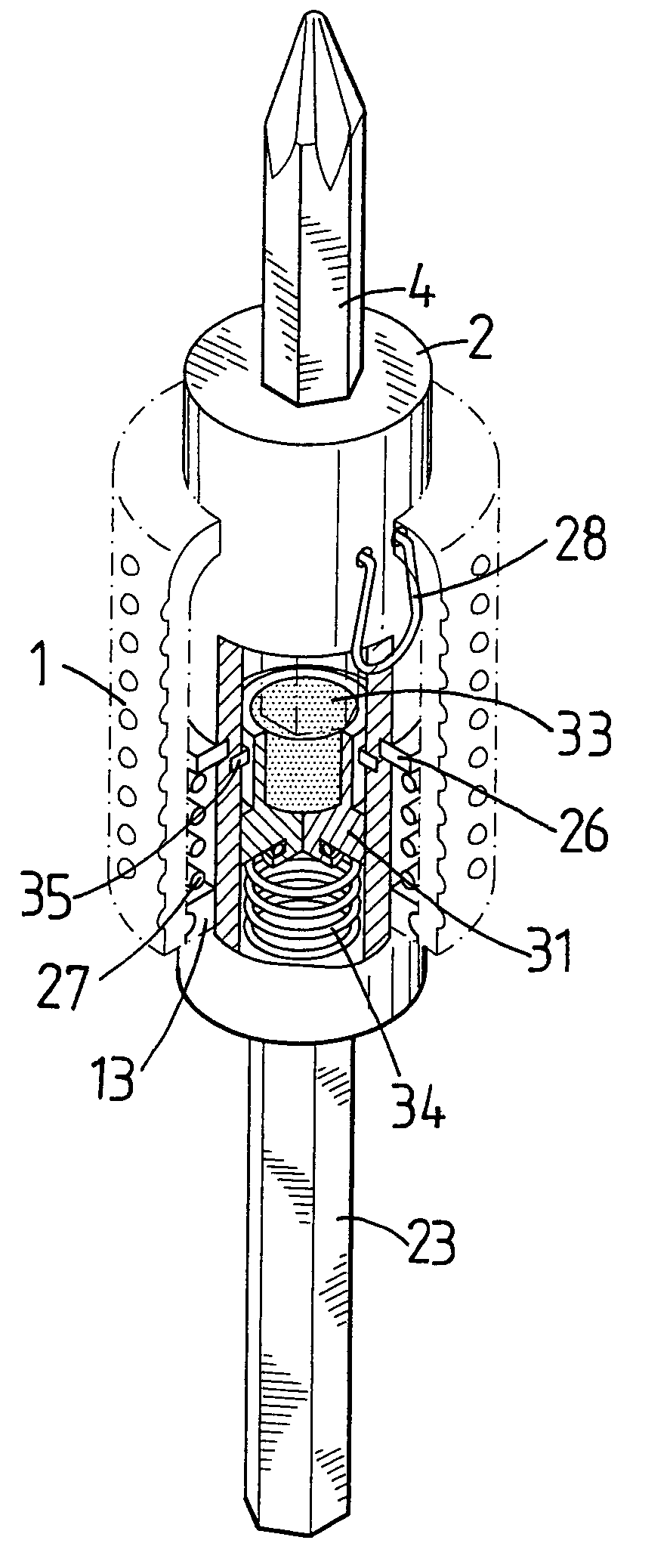
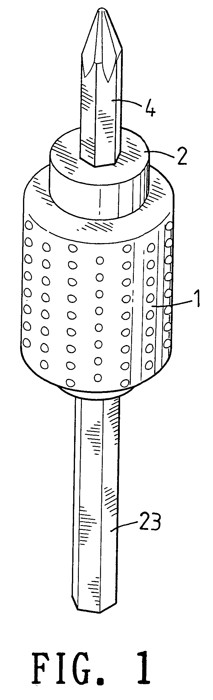
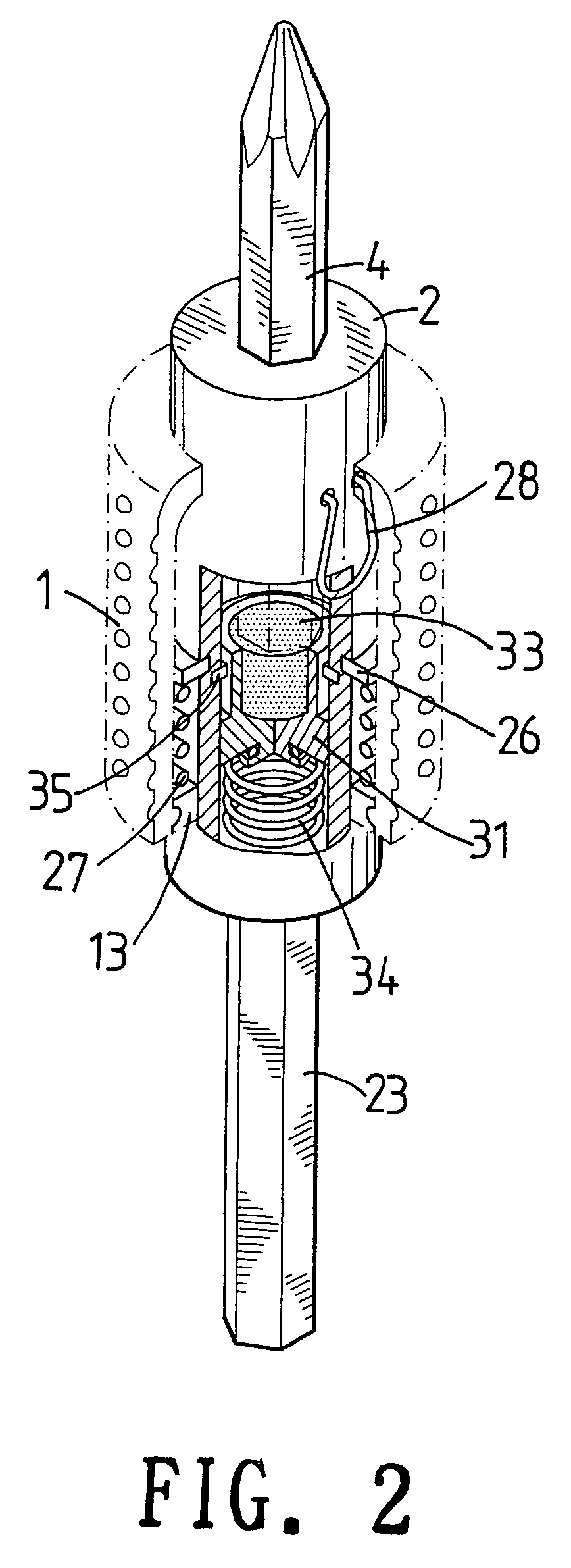
[0021]Referring to the drawings and initially to FIGS. 1–4, a socket assembly in accordance with the preferred embodiment of the present invention comprises an inner sleeve 2, an outer sleeve 1 movably mounted on the inner sleeve 2, a space 14 (see FIG. 4) defined between the inner sleeve 2 and the outer sleeve 1, and an attachment device 3 mounted in the inner sleeve 2.

[0022]The inner sleeve 2 has an inside formed with a hollow receiving chamber 21. The inner sleeve 2 has a first end formed with a hexagonal insertion recess 22 for insertion of a screwdriver head 4 which has a periphery formed with a positioning groove 41. The inner sleeve 2 has a second end provided with a connecting rod 23 which is extended outward from the inner sleeve 2. Preferably, the second end of the inner sleeve 2 has an inner wall formed with a screw bore 213 for screwing a threaded positioning cap 36, and the connecting rod 23 has an end secured on the positioning cap 36.

[0023]The outer sleeve 1 has an ou...


PUM


Abstract

A socket assembly includes an inner sleeve, an outer sleeve movably mounted on the inner sleeve, a space defined between the inner sleeve and the outer sleeve, and an attachment device mounted in the inner sleeve. Thus, the screwdriver head is locked by the locking member elastically, so that the screwdriver head can be mounted on and detached from the inner sleeve easily and conveniently, thereby facilitating the user mounting and removing the screwdriver head.

Description

BACKGROUND OF THE INVENTION[0001]1. Field of the Invention[0002]The present invention relates to a socket assembly, and more particularly to a socket assembly that can be mounted and detached easily and rapidly.[0003]2. Description of the Related Art[0004]A conventional socket comprises a socket body having an end formed with a hexagonal insertion recess for insertion of a screwdriver head which has a periphery formed with a positioning groove, and a positioning ball mounted in a cavity formed in the wall of the insertion recess of the socket body and locked in the positioning groove of the screwdriver head. Thus, the screwdriver head is fixed on the socket body by the positioning ball, so that the screwdriver head can be rotated by the socket body of the conventional socket.[0005]However, it is necessary to form the cavity in the wall of the insertion recess of the socket body for positioning the positioning ball, thereby greatly complicating the manufacturing procedure, and thereb...

Claims


Application Information

Patent Timeline
Patent Type & Authority Patents(United States)
IPC IPC(8): B25B15/00B25B23/00B25B23/12
CPCB25B15/001B25B23/0035B25B23/12B25B23/0057Y10T279/17811
Inventor HUANG, JUNG-CHIH
Owner HUANG JUNG CHIH
Why Eureka
Try Eureka