Retractable seats

Inactive Publication Date: 2005-12-13
ARACO CORP
View PDF20 Cites 20 Cited by
  • Summary
  • Abstract
  • Description
  • Claims
  • Application Information

AI Technical Summary

Benefits of technology

[0009]According to this retractable seat, the restraint mechanism may provide sufficient support strength to the seat when the seat is

Problems solved by technology

However, in the retractable seat that is supported by the links, the link rotation regulating function of the hinge means does not provide sufficient support strength to the seat when

Method used


Image

  • Retractable seats
  • Retractable seats
  • Retractable seats

Examples


Example

[0101]Because the second embodiment relates to the first embodiment, only the constructions and elements that are different from the first embodiment will be explained in detail. Elements that are the same in the first and second embodiments will be identified by the same reference numerals and a detailed description of such elements may be omitted.

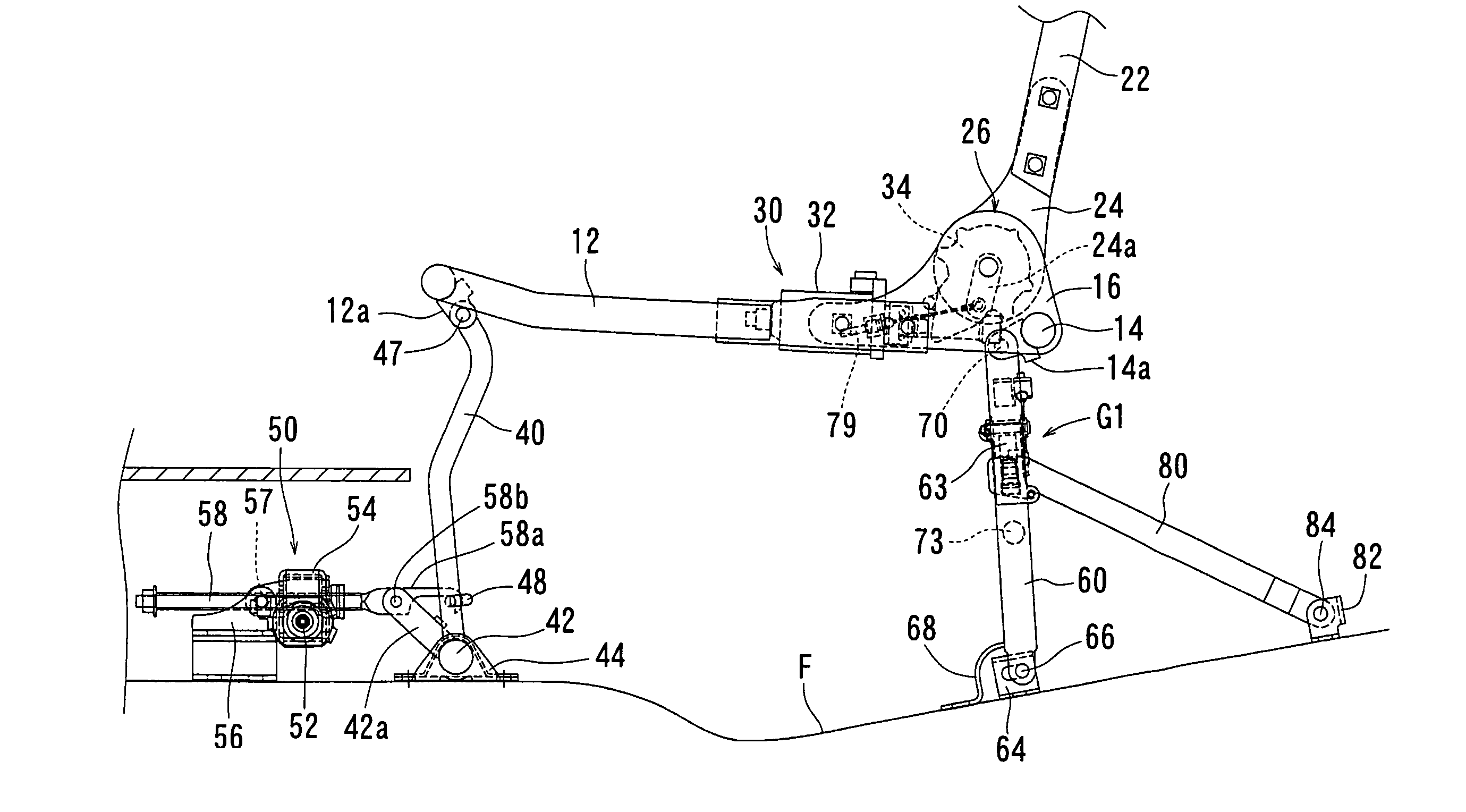
[0102]As shown in FIG. 18, in this embodiment the first connecting portion C1 is formed by a connecting portion of an end portion of a connection arm 42b and a forward end of the connection member 58a. As will be recognized, the connection arm 42b is fixed to the lower supporting member 42 of the front legs 40 and is inclined backwardly. Further, the second connecting portion C2 is formed by an engagement portion of the engagement member 48 of the front legs 40 and a hook 58a-2. In such a three-joint link thus formed, the leftward moving distance of the first connecting portion C1 is greater than the leftward moving distance of the second...

Example

[0104]Because the third embodiment relates to both the first and second embodiments, only the constructions and elements that are different from either the first and second embodiments will be explained in detail. Elements that are the same in the first to third embodiments will be identified by the same reference numerals and a detailed description of such elements may be omitted.

[0105]As shown in FIGS. 19 and 20, the seat cushion 10 is supported on the floor F by a pair of front legs 40 and a pair of rear legs 160. Similar to the first embodiment, the connection member 58a of the operating member 58 of the driving means 50 is connected to the connection arm 42a, fixed to the lower supporting member 42 of the front legs 40 via the connection pin 58b. However, unlike the first embodiment, the hooks 58a-1 and 58a-2 of the connection member 58a and the engagement member 48 of the front legs 40 are not used.

[0106]Lower end portions of the rear legs 160 are connected to bearing brackets...

Example

[0112]Because the fourth embodiment relates to the first to third embodiments, only the constructions and elements that are different from the first to third embodiments will be explained in detail. Elements that are the same in the first to fourth embodiments will be identified by the same reference numerals and a detailed description of such elements may be omitted.

[0113]As shown in FIG. 24, in this embodiment a lower end portion of each rear leg 260 is connected to a bearing bracket 264 fixed to the floor F via a hinge pin 266. An upper end portion of each of the rear legs 260 is connected to the cushion frame 12 via a hinge pin 270. Further, the rear legs 260 are supported from front sides thereof by means of support members 280 (i.e., restraint mechanism or support mechanism).

[0114]A lower end portion of each of the support members 280 is rotatably connected to the bearing bracket 282 fixed to the floor F via a hinge pin 284. An upper end portion of the support member 280 is su...


PUM


Abstract

A retractable seat may include a seat cushion, a seat back rotatably supported on the seat cushion, and a link mechanism for supporting the seat cushion on a floor. The link mechanism includes a front leg and a rear leg that are pivotally connected to the seat cushion and the floor so that the seat cushion and the seat back can be switched between a use condition and a retracted condition. The seat may further include a restraint mechanism provided on the floor for preventing the link mechanism from moving when the seat is in a use condition.

Description

BACKGROUND OF THE INVENTION[0001]1. Field of the Invention[0002]The present invention relates to retractable seats for a vehicle. More particularly, the present invention relates to retractable seats in which the seat can be retracted when a seat cushion is brought down to the floor by means of a link mechanism.[0003]2. Description of the Related Art[0004]A retractable seat of this type is taught, for example, by Japanese Laid-Open Patent Publication No. 2002-316567.[0005]In the known art, the seat is vertically movably supported on a vehicle floor by means of front and rear links. A hinge means provided on a seat support point of the rear link has a rotation restriction function for preventing the rotation of the rear link. Due to this rotation restriction function, the seat can be maintained in a retracted condition in which the seat is retracted into a receiving recess formed in the vehicle floor and maintained in a use condition in which the seat is positioned above the receivin...

Claims


Application Information

Patent Timeline
IPC IPC(8): B60N2/30B60N2/48
CPCB60N2/3011B60N2/3065B60N2/3072B60N2/309B60N2/4832B60N2002/4891B60N2002/0236B60N2002/024B60N2/891B60N2/832B60N2/02258B60N2/02253
Inventor IMAJO, TAKUOOTSUKA, TAIYOU
Owner ARACO CORP
Why Eureka
Try Eureka