Driveable catheter system

a technology of driving catheter and drive shaft, which is applied in the direction of catheter, application, ultrasonic/sonic/infrasonic diagnostics, etc., can solve the problems of limited blood flow, serious risk to the health of people, and constant translational rate of the device, so as to simplify the translational movement and facilitate the user's setup

Inactive Publication Date: 2005-12-13
BOSTON SCI SCIMED INC
View PDF24 Cites 62 Cited by
  • Summary
  • Abstract
  • Description
  • Claims
  • Application Information

AI Technical Summary

Benefits of technology

This patent describes an improved driver for a catheter that uses less than one clean cover and doesn't have any electricity running through it. It also makes it easier to move around because there aren't any heavy parts attached. The device has a display that shows how far the catheter has moved during operation. Both the controller and the driver communicate back and forth, making it simpler to adjust settings and operate the machine.

Problems solved by technology

The technical problem addressed in this patent is how to create a catheter system that has the ability to move back and forth inside a patient's blood vessels without causing any damage or delay during treatment. Current methods involve either moving the whole machine back and forth or relying on automated movements that often struggle to keep up with the speed needed for optimal results. Additionally, current methods make it hard for medical professionals to accurately determine the location of the treatment area due to limitations in image resolution.

Method used


Image

  • Driveable catheter system
  • Driveable catheter system
  • Driveable catheter system

Examples


Embodiment Construction

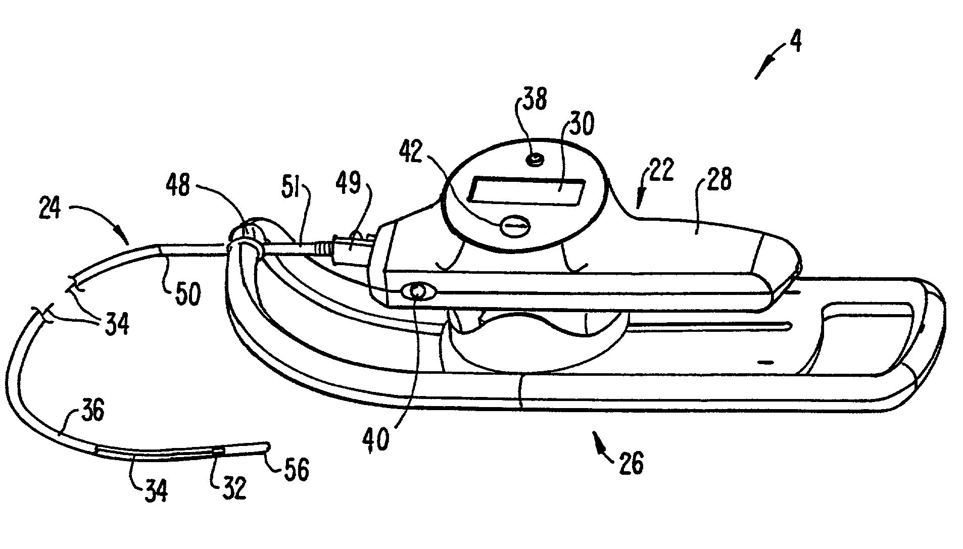
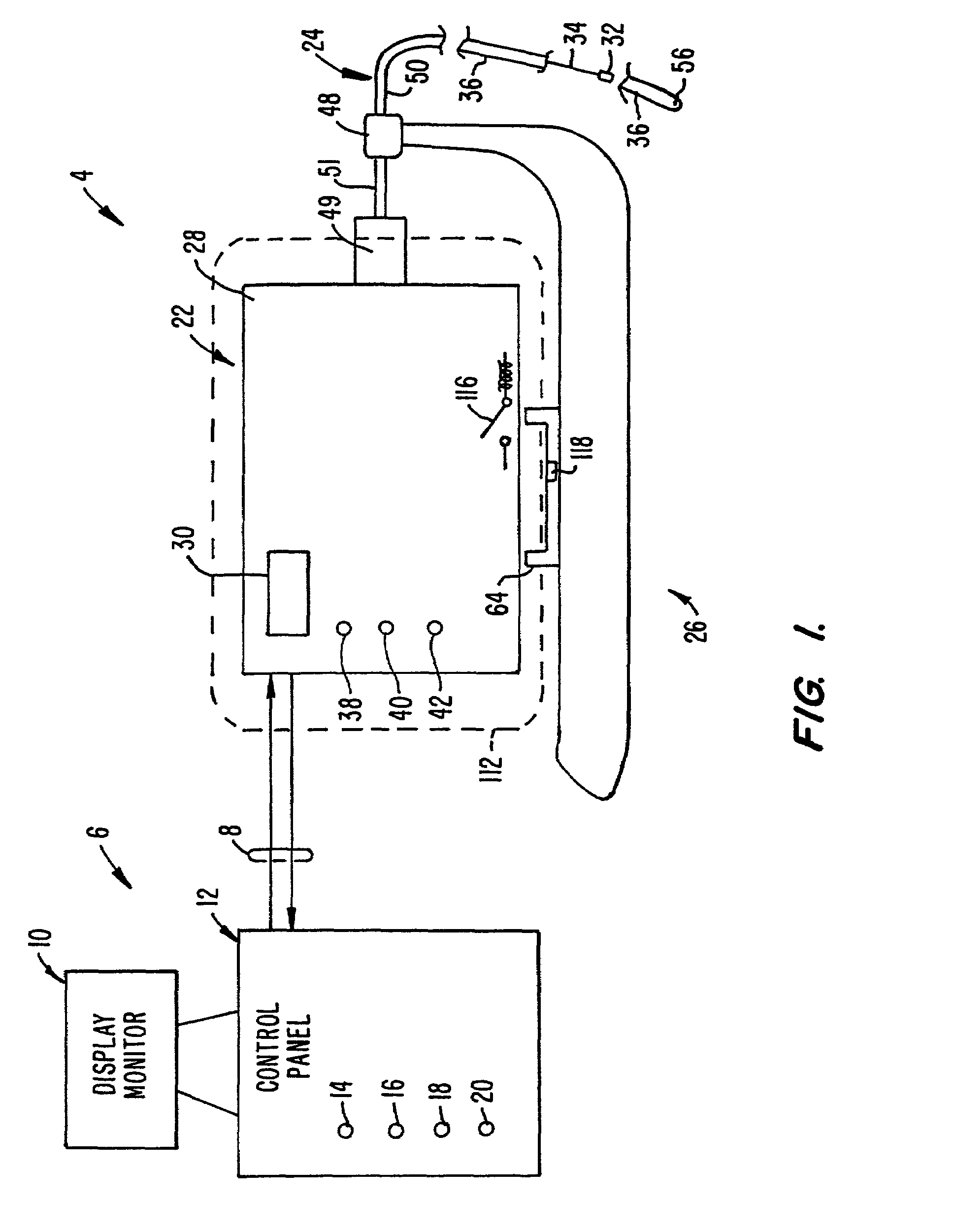
[0027]FIG. 1 schematically illustrates a driveable catheter system 2 made according to the invention. System 2 includes broadly a driveable catheter assembly 4 operably coupled to a control unit 6 through a two-way data and communication link 8. One such two-way communication link includes an RS232 communication link which permits information and data from catheter assembly 4 to be directed to control unit 6 and permits instructions and control signals to be provided to driveable catheter assembly 4 from control unit 6.

[0028]Control unit 6 includes a display monitor 10 providing display of translation displacement information as well as other information. Control unit 6 also includes a control panel 12 which may include, for example, an alphanumeric keyboard, dedicated input buttons or a combination thereof. Other type of inputs including voice command input or a touch screen type of input can also be provided by control unit 6. In particular, control panel 12 provides for rotator d...


PUM


Abstract

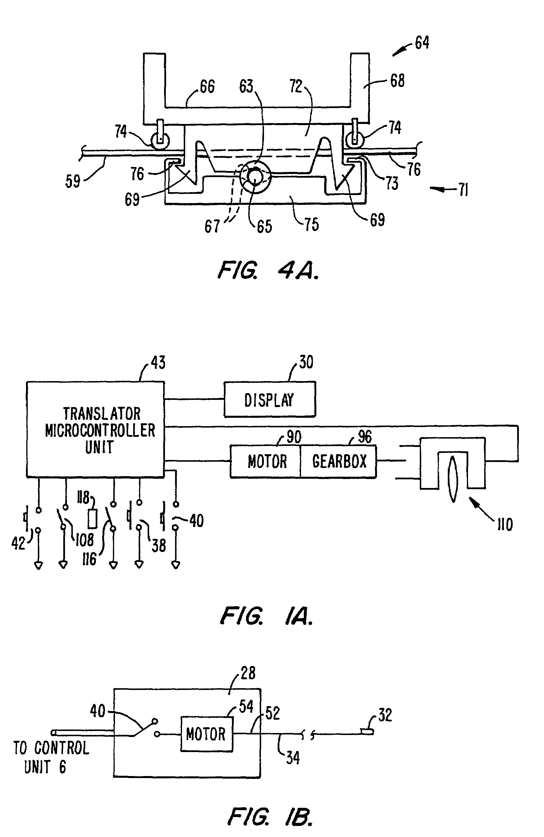
The system (2) includes a catheter drive unit (22) and a catheter (24) extending therefrom movably mounted to a catheter drive sled (26). The catheter drive unit rotates and translates the catheter core (34) within the catheter sheath (36). The sled has a serrated, conical drive unit interface (82), with a bag-piercing tip (86) mateable with a translator drive ouput (92) so that a sterile drape (112) enclosing the catheter drive unit is automatically pierced when the catheter drive unit is mounted to the sled. A control unit (6) is spaced apart from the catheter drive unit and provides power and commands to the catheter drive unit and receives information and data from the catheter drive unit. The rotator and translator drive motors (54, 90) are operated from both the control unit and the catheter drive unit. Both the control unit and catheter drive unit have translation displacement displays (10, 30).

Description


Claims


Application Information

Patent Timeline
Owner BOSTON SCI SCIMED INC
Why Eureka
Try Eureka