Imaging catheter

a catheter and imaging technology, applied in the field of medical imaging, can solve the problems of increasing the setup time, complicating the procedure, and affecting the patient's clinical experience, and achieve the effects of convenient catheter guide, light weight, and convenient handling and maneuvering

Active Publication Date: 2009-10-29
BOSTON SCI SCIMED INC
View PDF36 Cites 73 Cited by
  • Summary
  • Abstract
  • Description
  • Claims
  • Application Information

AI Technical Summary

Benefits of technology

[0008]In an exemplary embodiment, a catheter comprises a handle assembly having distal and proximal ends, a catheter sheath connected to the distal end of the handle assembly, and an elongated flexible tube connected to the proximal end of the handle assembly. The catheter further comprises an imaging core slidably received within the catheter sheath, the handle assembly and the elongated tube. The imaging core includes a slide member, e.g., knob, extending from the imaging core and passing through an elongated slot in the handle assembly, allowing a physician to manually pullback and advance the imaging core within the catheter by sliding the slide member back and forth. Preferably, the elongated tube is long enough so that the motor drive unit (MDU) coupled to the p

Problems solved by technology

Current IVUS systems suffer from several drawbacks.
One drawback is that the MDU is in the sterile field and therefore must be covered, e.g., by a sterile bag, which increases the setup time.
Also, the physician must handle the MDU to guide the c

Method used


Image

  • Imaging catheter
  • Imaging catheter
  • Imaging catheter

Examples


Embodiment Construction

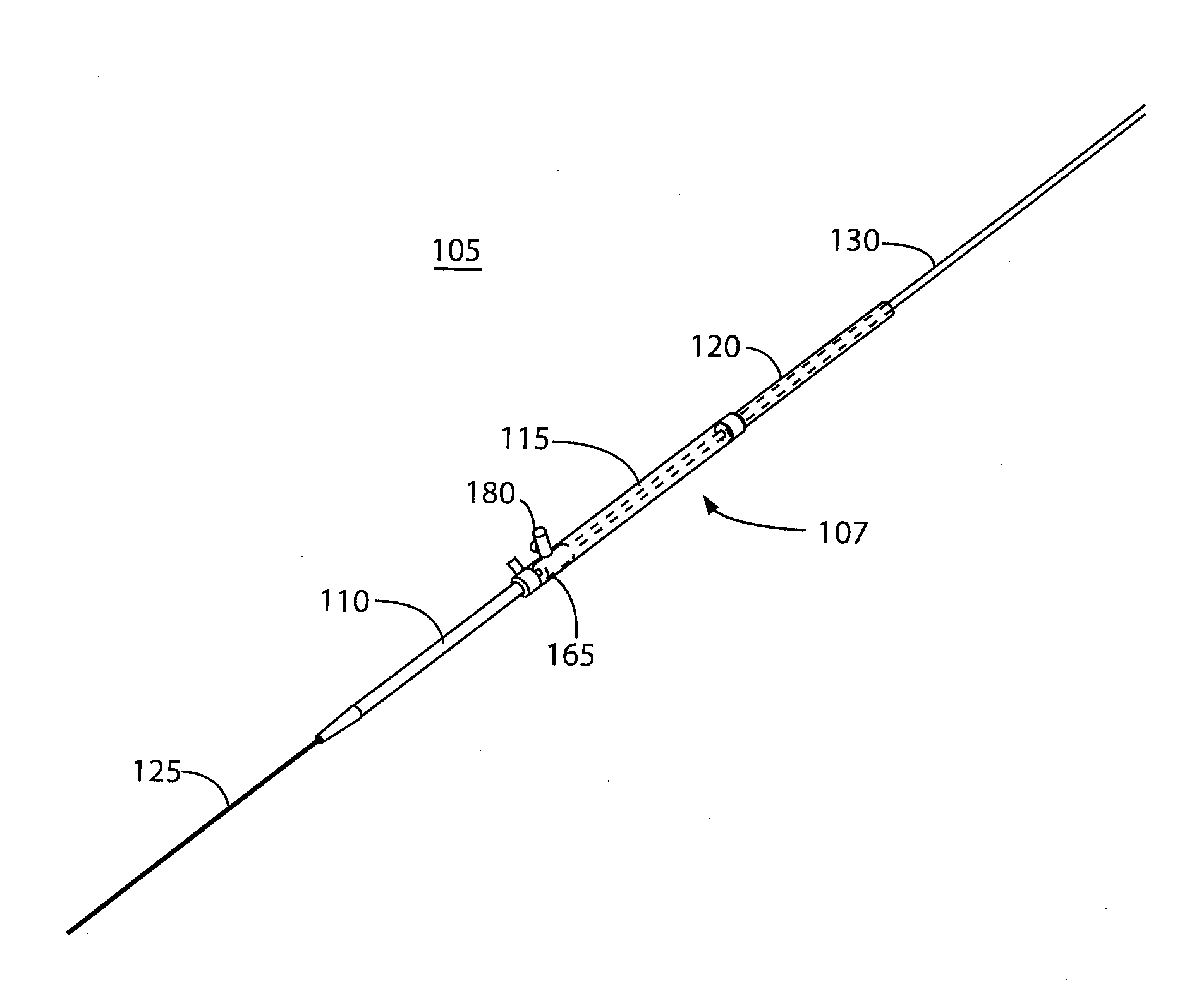
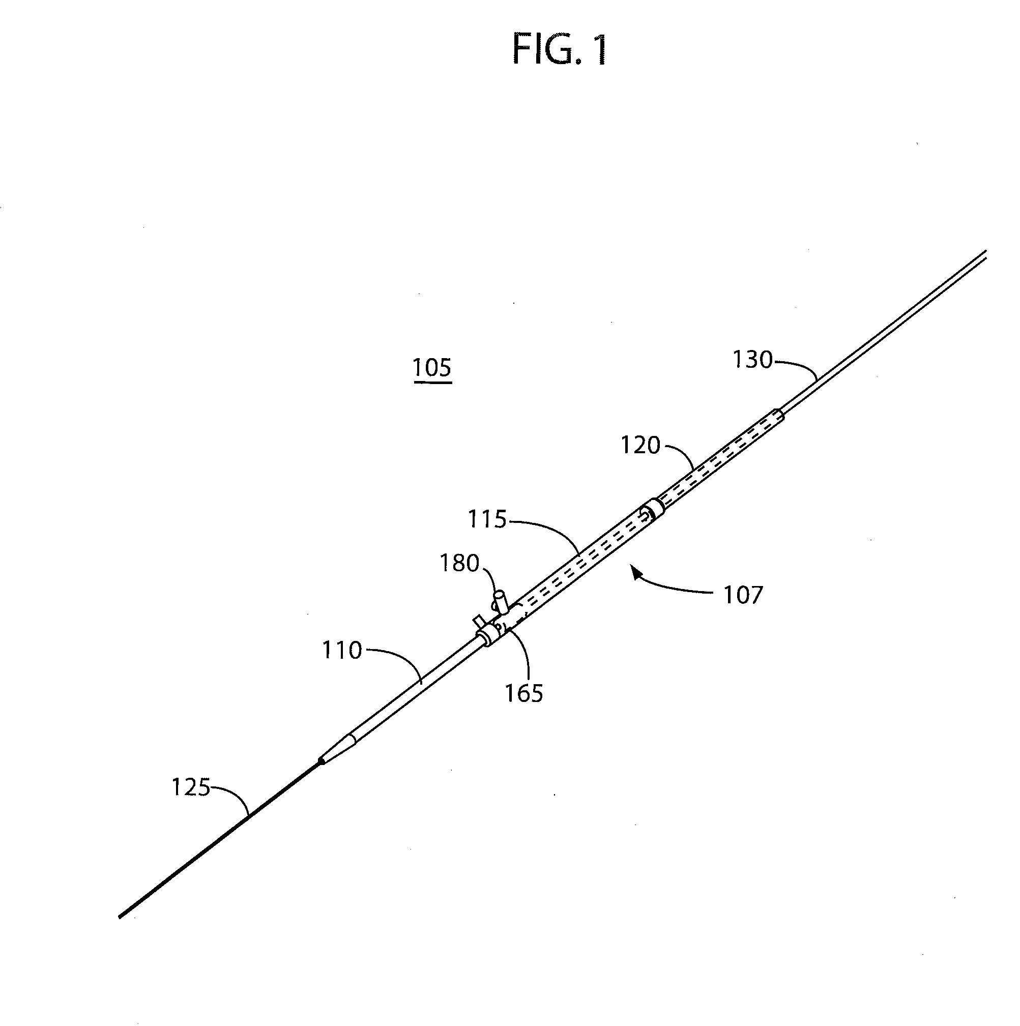
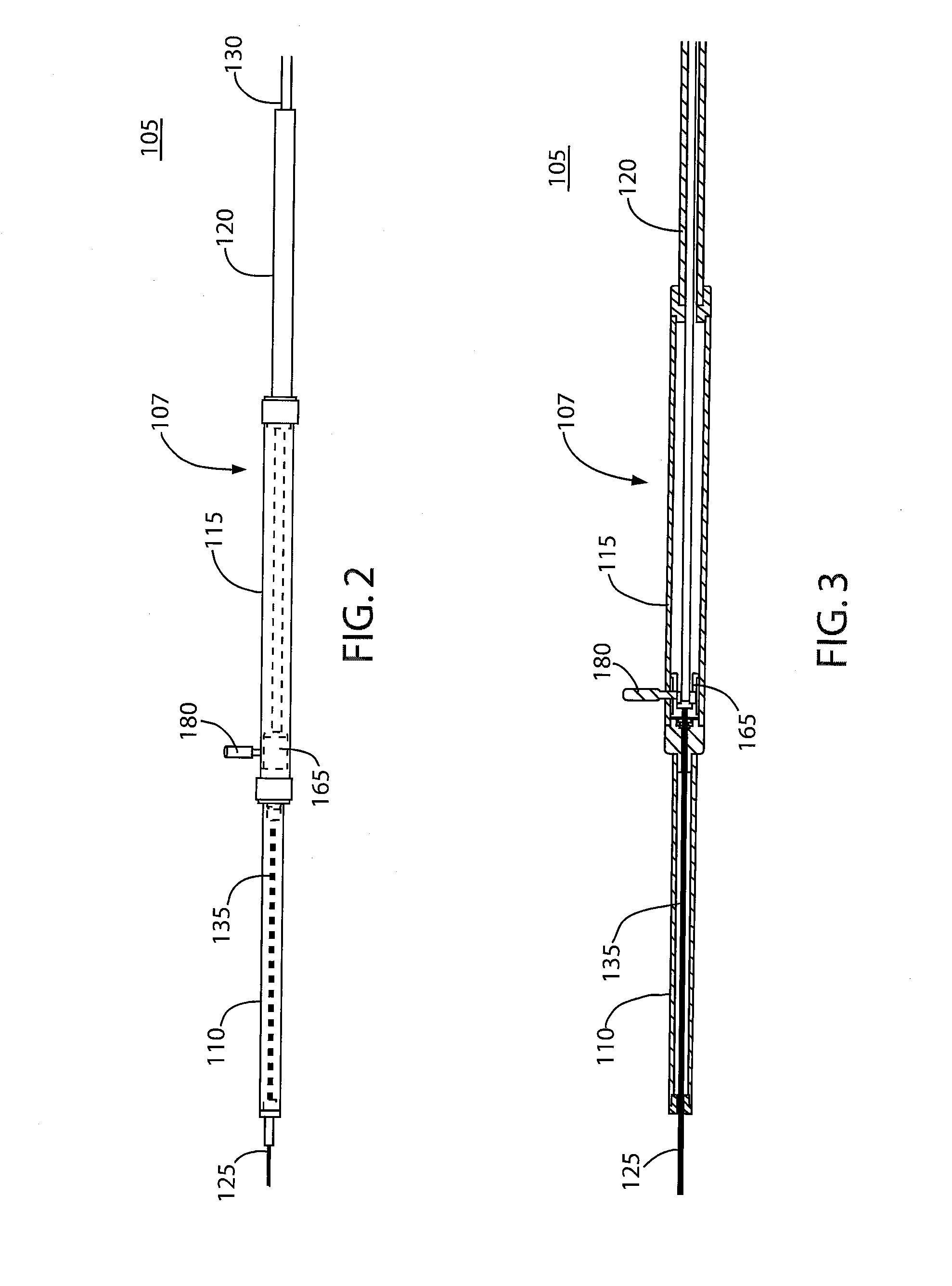
[0026]FIGS. 1-3 show a catheter system 105 according to an embodiment of the present invention. The catheter system 105 comprises a handle assembly 107 comprising a distal tube 110, a slotted tube 115, and a proximal tube 120. The distal and proximal tubes 110, 120 are connected to opposite ends of the slotted tube 115. The catheter system 105 further comprises a catheter sheath 125 connected to the distal end of the distal tube 110, and an outer jacket 130 connected to the proximal end of the proximal tube 120. The catheter sheath 125 is preferably an intravascular catheter sheath adapted to be inserted into a blood vessel, and may be made of a polymeric material, such as polytetrafluoroethylene (PTFE), polyethylene, PEEK, PEBAX or other suitable material. The catheter system 105 also comprises a female telescope tube 135 housed within the distal tube 110. The distal tube 110, slotted tube 115, and proximal tube 120 may be made of polycarbonate, e.g., transparent polycarbonate.

[002...


PUM


Abstract

Described herein are imaging catheter system. In an exemplary embodiment, a catheter comprises a handle assembly having distal and proximal ends, a catheter sheath connected to the distal end of the handle assembly, and an elongated flexible tube connected to the proximal end of the handle assembly. The catheter further comprises an imaging core slidably received within the catheter sheath, the handle assembly and the elongated tube. The imaging core also includes a slide member, e.g., knob, extending from the imaging core and passing through an elongated slot in the handle assembly, allowing a physician to manually pullback and advance the imaging core within the catheter by sliding the slide member back and forth. Preferably, the elongated tube is long enough so that the motor drive coupled to the proximal end of the catheter is kept outside the sterile field during the imaging procedure.

Description

FIELD OF THE INVENTION[0001]The present invention relates to medical imaging, and more particularly to medical imaging catheters.BACKGROUND INFORMATION[0002]Intravascular ultrasound imaging systems (IVUS) are used to obtain ultrasound images inside a patient's body. An IVUS system typically includes an ultrasound catheter having a flexible catheter sheath adapted for insertion into the vascular system of the patient. To obtain ultrasound images, the catheter comprises an imaging core received within a lumen of the catheter sheath. The imaging core comprises an ultrasound transducer attached to the distal end of a long flexible drive cable and an electrical and mechanical connector at the proximal end of the drive cable. The drive cable is used to rotate and longitudinally translate the transducer within the catheter lumen to obtain images at different positions within the patient's body.[0003]The catheter may include a telescoping section that allows the imaging core to be advanced ...

Claims


Application Information

Patent Timeline
IPC IPC(8): A61B8/14
CPCA61B8/12A61M25/00A61B8/445
Inventor THORNTON, PETER
Owner BOSTON SCI SCIMED INC
Why Eureka
Try Eureka