Total vascular occlusion treatment system and method

a technology of vascular occlusion and treatment system, applied in the field of medical devices, can solve the problems of increasing morbidity, increasing the risk of ctosis, and progressing for a long time, and achieve the effect of inhibiting the resistance of ctosis

Inactive Publication Date: 2008-02-07
EMERGE MEDSYST
View PDF14 Cites 63 Cited by
  • Summary
  • Abstract
  • Description
  • Claims
  • Application Information

AI Technical Summary

Benefits of technology

[0048] Another aspect is a medical device system for providing vascular access across a chronic total occlusion (“CTO”) within a body of a patient. This aspect includes a catheter comprising a first elongate body with a proximal end portion, a distal end portion, and a guide wire lumen with a distal port at the distal end portion, and a guide wire having a second elongate body with a proximal end portion and a distal end portion that extends along a first longitudinal axis with a first outer diameter. A distal tip section is located on the distal end portion of the guide wire. The distal tip section has a second outer diameter and a length along a second longitudinal axis between a proximal end and a distal end. The second longitudinal axis is angled relative to the first longitudinal axis. The second outer diameter is greater than the first outer diameter such that the distal tip section is radially enlarged relative to the distal end portion of the second elongate body. The second elongate body of the guide wire is configured to be rotatably disposed at least in par

Problems solved by technology

Recanalization of CTO's remains a leading indication for invasive open heart surgery, unapproachable by most less invasive catheter therapies.
Thus, CTO's are a frequent cause for patients to be referred instead to the highly invasive (and increased morbidity) option of open heart coronary artery bypass surgery.
In another regard, the heart is more sensitive to compromised flow than the legs, and thus earlier progression of disease becomes critically symptomatic—the peripheral vessels thus may progress for much longer periods of time before symptoms become critical for locomotion, etc.
The extreme measures of open heart surgery or leg amputation, respectively, for coronary and peripheral CTO's are unfortunate when so many percutaneous translumenal systems and treatment methods have emerged for treating vascular occlusions with significantly reduced invasion and morbidity, in fact sometimes even done on an “out patient” basis.
However, such methods have been associated with as high as about 30% “restenosis” rates, wherein the body's own response to the controlled balloon or ablation injury scars and reblocks the vessel, sometimes to a worse condition than before the intervention.
All of these treatments however share a common obstacle that has prevented their significant use in treating total occlusions—they all generally require some remaining lumen through the occlusion in order to perform the recanalization function (or “open the vessel”) as intended.
Angioplasty balloons, stents, and some atherectomy devices as noted above, further suffer from the requirement that they be positioned in a lumen within the lesion in order to perform their job to open or recanalize the area.
However, even these devices and related techniques still typically require the guidewire as a rail to direct the ablation process through the lesion else it may go astray and cause unintended and dangerous damage through the vessel wall.
In other cases, however, all attempts fails.
And, in certain circumstances, more injury may have been caused by the failed attempt, such as either causing a dissection in the vessel wall that may propagate upstream to a more proximal (and thus more dangerous) area of instability, or by perforating the vessel wall with the wire which may cause blood loss tha

Method used


Image

  • Total vascular occlusion treatment system and method
  • Total vascular occlusion treatment system and method
  • Total vascular occlusion treatment system and method

Examples


Embodiment Construction

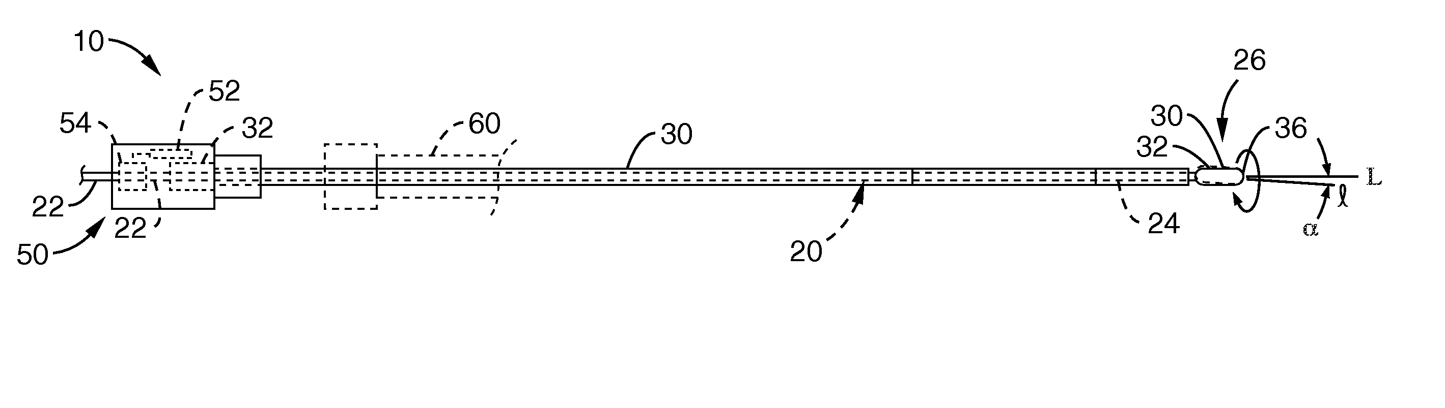
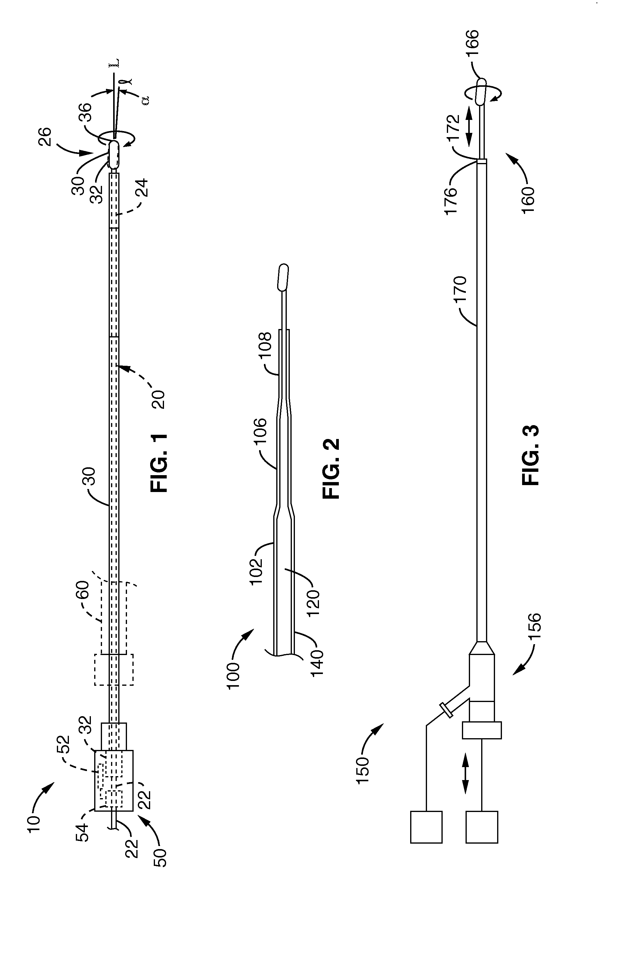
[0082] As shown in FIG. 1, the invention includes a chronic total occlusion (CTO) crossing system 10 with a wire 20 located coaxially within an outer tubular sheath 40. The wire includes a distal tip 26 extending beyond the distal end 36 of the tubular sheath. The proximal end portions 22, 32 of each of the wire 20 and tubular sheath 30, respectively, are coupled to an actuator assembly 50 in such a manner that the wire 20 is mechanically spun by a motor 52 coupled to the wire via a coupler 54 and so that the wire 20 spins within the outer tubular sheath 40.

[0083] The wire's distal tip 26 includes an enlargement 30 that, in the illustrative embodiment shown in FIG. 1, is constructed and oriented in a specific and particularly beneficial manner as follows. The enlargement 30 has a length along a longitudinal axis I that extends between a proximal end 32 and a distal end 36. The enlargement 30 is canted relative to a core 24 of wire 20 to which the enlargement 30 is secured such that...


PUM


Abstract

A system is provided for providing vascular access across chronic total occlusions, in particular those that are particularly long such as in the lower periphery. A guide wire has an off-set, tilted tip section that provides rotational micro-dissection through tight CTO lesions. An outer catheter sheath prevents binding of the wire via wire reinforced composite polymeric construction. The outer sheath catheter includes an ablative outer surface for ablating tissue in contact therewith. The guide wire and outer sheath catheter are each driven by an actuator for cooperative advancement through the CTO. Rotational couplers rotate them, which may be at different speeds and via different couplers. The engagement of the wire within the sheath may allow for at least limited longitudinal movement between them during CTO advancement. Aspiration of ablated debris around the outer rotational ablation catheter is accomplished through suction ports through the composite wall and between adjacent windings of the reinforcement. Long CTOs of the peripheral vasculature are in particular benefited by the assembly, which allows on-going force transmission to the distal components through long portions of blockage, and allows for pilot lumen formation for advancing other interventional tools.

Description

CROSS-REFERENCE TO RELATED APPLICATIONS [0001] This application claims priority from, and is a 35 U.S.C. § 111(a) continuation of, co-pending PCT international application serial number PCT / US2006 / 004222, filed on Feb. 2, 2006, incorporated herein by reference in its entirety, which claims priority from U.S. provisional application Ser. No. 60 / 649,506, filed on Feb. 2, 2005, incorporated herein by reference in its entirety. [0002] This application is related to PCT international Publication No. WO / 2006 / 084256, published on Aug. 10, 2006, incorporated herein by reference in its entirety.STATEMENT REGARDING FEDERALLY SPONSORED RESEARCH OR DEVELOPMENT [0003] Not Applicable NOTICE OF MATERIAL SUBJECT TO COPYRIGHT PROTECTION [0004] A portion of the material in this patent document is subject to copyright protection under the copyright laws of the United States and of other countries. The owner of the copyright rights has no objection to the facsimile reproduction by anyone of the patent ...

Claims


Application Information

Patent Timeline
IPC IPC(8): A61B18/14
CPCA61B17/320016A61B2017/320032A61B17/32002
Inventor PEACOCK, JAMES C. III
Owner EMERGE MEDSYST
Why Eureka
Try Eureka