Headphone with restraint and methods

a headphone and restraint technology, applied in the direction of transducer details, earpiece/earphone attachment, electrical transducer, etc., can solve the problems of stiff headphone wires, unable to easily move out of the way of users, and headphones still tangle, etc., and achieve the effect of sliding resistance of the restrain

Inactive Publication Date: 2013-01-01
PANG JEFFREY +3
View PDF14 Cites 32 Cited by
  • Summary
  • Abstract
  • Description
  • Claims
  • Application Information

AI Technical Summary

Benefits of technology

[0007]In operation, after the user removes her headphones, she grasps the restraint and repositions the restraint towards the ear buds (passing over a microphone, if present), and then inserts the audio input jack into the groove, slot, channel of the restraint, sometimes physically adjacent to the ear buds. The sliding resistance of the restraint with respect to the wires / input jack increases, when the audio input jack is inserted into the restraint.

Problems solved by technology

Prior art techniques to solving the tangling problem have including using thicker headphone wire or insulation, but such techniques have drawbacks including that the headphone wires are stiff and do not easily move out of the users' way.
Other techniques have included a wire pull between the wires leading to the ear buds, but such techniques have drawbacks including that such headphones still tangle and the pull often fails to keep the ear buds together.
Other techniques have included an automatic spooling mechanism for the headphone wires, but such techniques have drawbacks including that the spooling mechanism is bulky, not aesthetically pleasing, and it causes a lot of stress on the wires.
Other techniques have included winding the wires upon an object such as a piece of plastic or the user's fingers, which is a time consuming process.
These problems especially significant with headphones with in-line microphones.
The in-line microphone typically interferes with any winding or sliding mechanism because they are often bulky and they are rigid, not flexible.

Method used


Image

  • Headphone with restraint and methods
  • Headphone with restraint and methods
  • Headphone with restraint and methods

Examples


Embodiment Construction

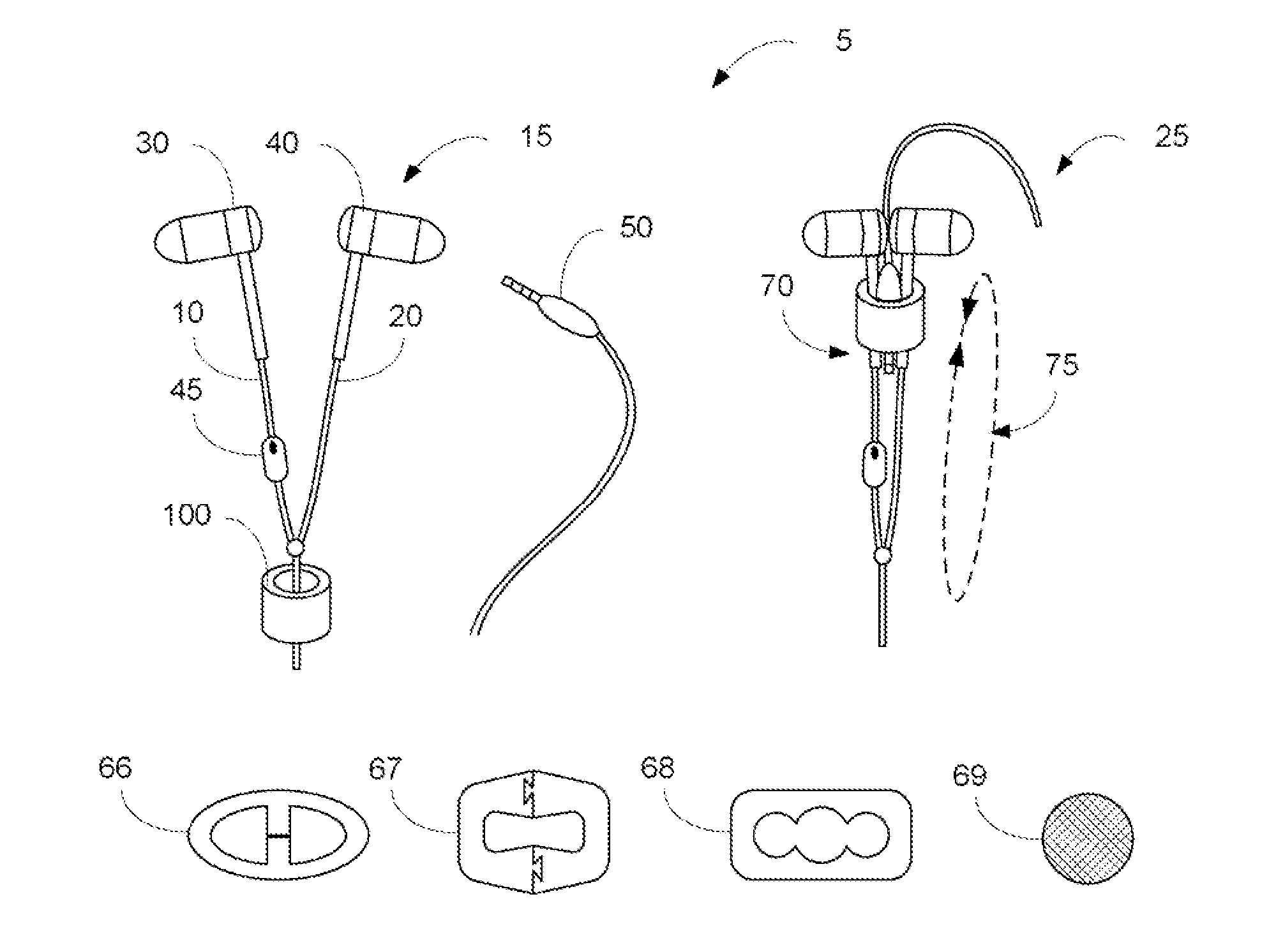
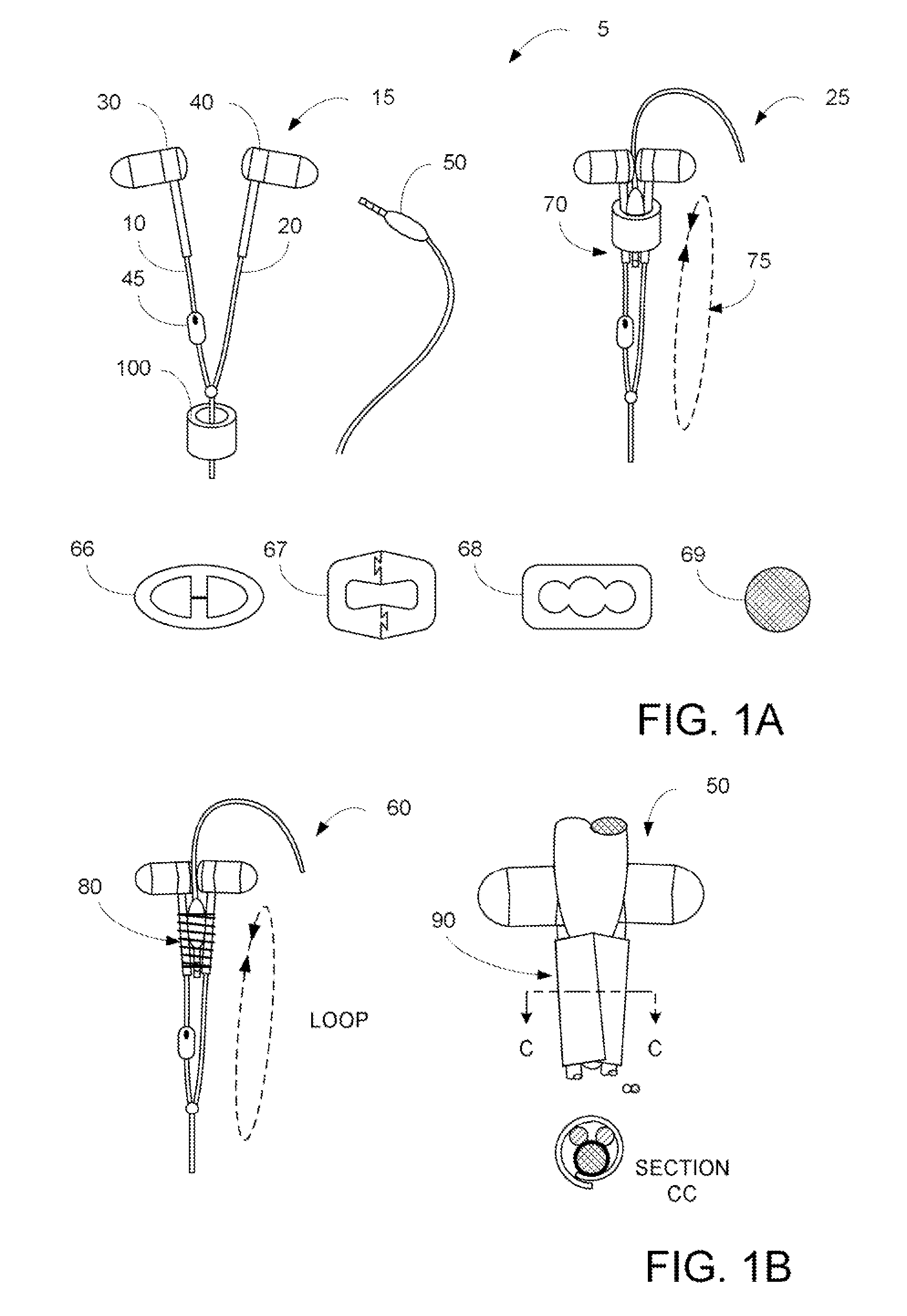
[0016]FIGS. 1A-B illustrates embodiments of the present invention. FIG. 1A illustrates a pair of earphones (ear buds) 5 in different configurations. As illustrated, ear buds 5 typically include ear buds 30 and 40 (that are typically inserted or placed upon a user's ears to provide audio outputs), an audio input (output) 50 (that is inserted into an audio device for receiving electrical outputs), wires 10 and 20 (coupling ear buds 30 and 40 to audio input 50), and (optionally) an in-line microphone 45 (that receives audio input from the user and provides it to the audio input / output 50). In various embodiments, in-line microphone 45 may include additional functionality such as volume buttons, control buttons, or the like.

[0017]In various embodiments, while in configuration 15, restraint 100 is positioned away from ear buds 30 and 40, and does not appreciably restrain ear buds 30 and 40 or audio input 50 with respect to each other. Thus, the user may freely plug in ear buds 30 and 40 ...


PUM


Abstract

A headphone having reduced-tangling potential includes an audio plug for receive electrical signals from an audio device, coupled via wires to ear buds, wherein the ear buds are for receiving electrical signals and outputting audio, wires coupled to the audio plug and to the pair of ear buds, wherein the coupling wire is configured to provide the electrical signals from the audio plug to at least the pair of ear buds, and a restraint device having a pliable material body having an interior channel, wherein the channel restrains movement of the separate ear buds a first resistance, when the audio plug is inserted into the channel, and wherein the channel restrains movement the separate ear buds by a second resistance, when the audio portion is separated from the channel, wherein the first resistance amount exceeds the second resistance amount.

Description

BACKGROUND OF THE INVENTION[0001]Embodiments of the present invention relate to wired headphones capable of being stored in a configuration with reduced tangling tendency and methods thereof.[0002]The inventors of the present invention have had many instances when they removed headphones (e.g. ear bud-type headphones) from a storage location (e.g. a pocket, a backpack), the headphones are tangled in a large mass of wires. In some instances, the inventors have had to spend minutes untangling a headphone cord before they can even use them. Accordingly, the inventors desired a headphone that had a reduced tendency to tangle.[0003]Prior art techniques to solving the tangling problem have including using thicker headphone wire or insulation, but such techniques have drawbacks including that the headphone wires are stiff and do not easily move out of the users' way. Other techniques have included a wire pull between the wires leading to the ear buds, but such techniques have drawbacks inc...

Claims


Application Information

Patent Timeline
Patent Type & Authority Patents(United States)
IPC IPC(8): H04R1/10
CPCH04R1/1033
Inventor PANG, JEFFREYPANG, CAROLINEPANG, DAVIDPANG, STEPHEN Y. F.
Owner PANG JEFFREY
Why Eureka
Try Eureka