Pressure-sensitive touch panel

a touch panel and pressure-sensitive technology, applied in the field of pressure-sensitive touch panels, can solve the problems of input coordinates being input unintended and erroneously positioned, and achieve the effect of preventing the input of position data erroneously

Inactive Publication Date: 2005-12-13
NEC INFRONTIA CORP
View PDF9 Cites 73 Cited by
  • Summary
  • Abstract
  • Description
  • Claims
  • Application Information

AI Technical Summary

Benefits of technology

[0008]Therefore, an object of the present invention is to provide a pressure-sensitive touch panel capable of preventing position data from being erroneously input, regardless of a pressing position by an operator. Another object of the present invention is to provide a pressure-sensitive touch panel capable of preventing the first transparent conductive film on the flexible insulating plate from damage.

Problems solved by technology

However, pressing force of the operator who inputs while holding the window frame bends the window frame and might cause unintended and erroneous position data of input coordinates.

Method used


Image

  • Pressure-sensitive touch panel
  • Pressure-sensitive touch panel
  • Pressure-sensitive touch panel

Examples


first embodiment

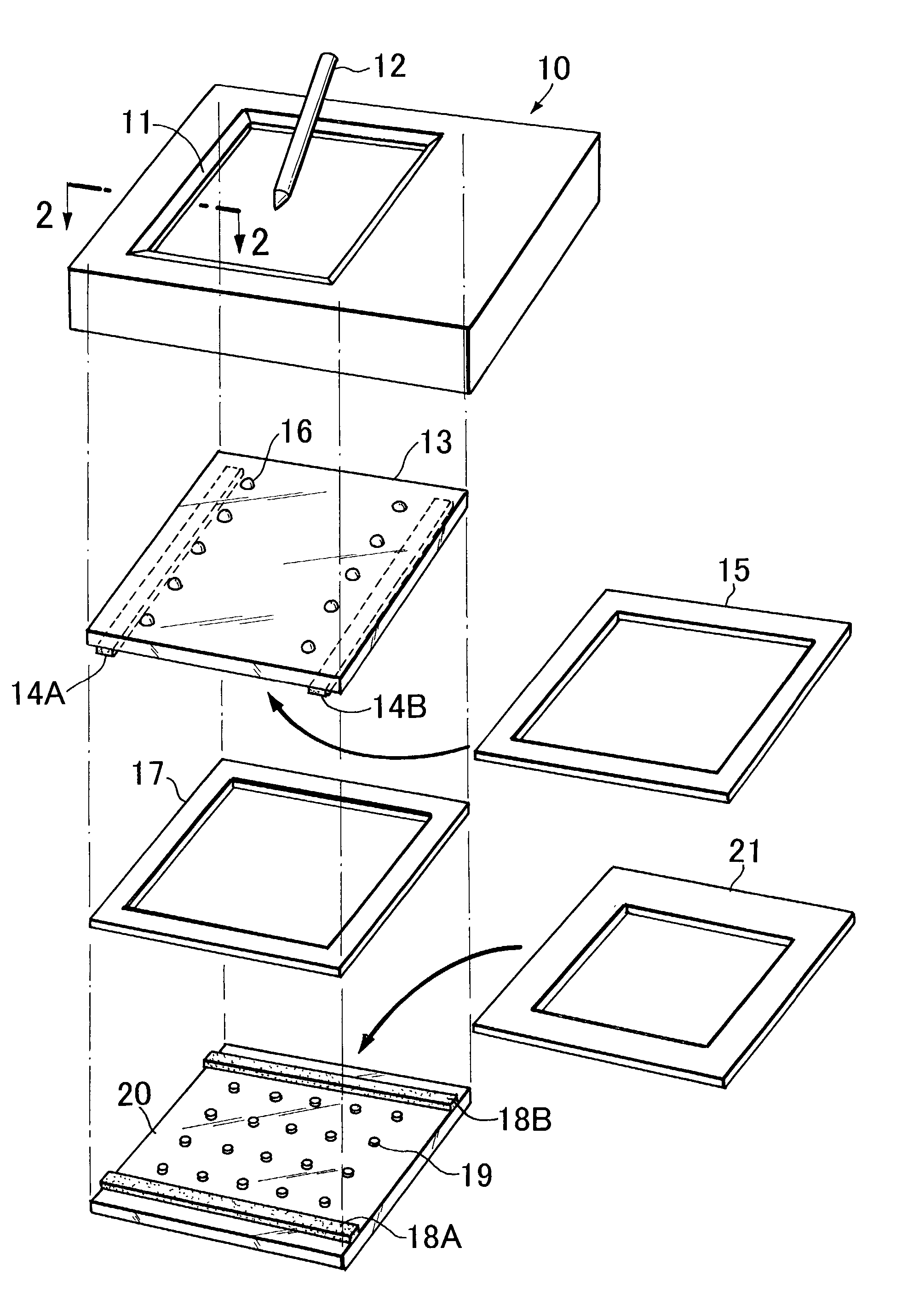
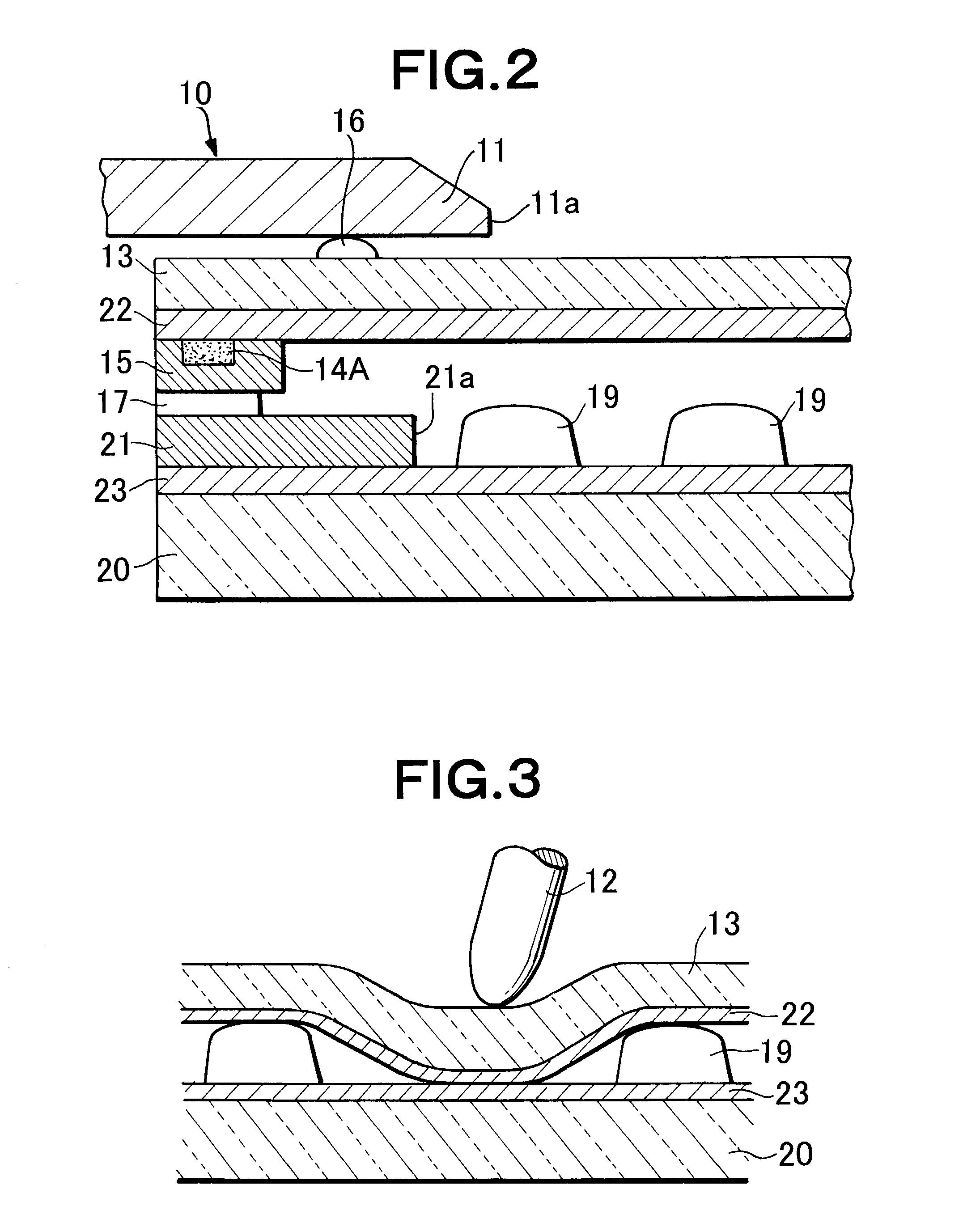
[0017]FIG. 1 is an exploded view showing the structure of the pressure-sensitive touch panel of the present invention, and FIG. 2 is a longitudinal sectional view in correspondence with 2—2 section in FIG. 1. FIG. 2 shows the thickness of a component in an exaggerated form, as compared to directions of the width and length thereof. In FIG. 1, transparent conductive films 22 and 23 are omitted.

[0018]FIG. 3 is a longitudinal sectional view in case of pressing the flexible insulating plate with a special pen.

[0019]For the inside of cabinet 10 of a pressure-sensitive touch panel, flexible insulating plate 13 in which transparent conductive film 22 is formed on an inner surface side and glass plate (as an insulating plate) 20 in which transparent conductive film 23 is formed on an inner surface side in a similar manner are disposed oppositely so as to sandwich a predetermined gap.

[0020]The conductive film 22 is provided with conductors 14A and 14B disposed along opposite two sides of the...

second embodiment

[0030]Next, the pressure-sensitive touch panel of the present invention will be described with a longitudinal sectional view of FIG. 4.

[0031]In FIG. 4, the difference from the structure of FIGS. 1 and 2 shown in the first embodiment is in that the position of the protrusion is changed, and the others are the same as those in FIGS. 1 and 2.

[0032]In other words, protrusion (as second spacers) 24 is provided on an inner surface side of the insulating layer 21 at an intermediate position between the inner periphery of the insulating layer 21 and the inner periphery of the insulating layer 15 at predetermined intervals.

[0033]Also in the pressure-sensitive touch panel constituted in this manner, when the window frame 11 bended by press force of an operator presses the flexible insulating plate 13, or the special pen 12 presses or slides over the flexible insulating plate 13 near to the inner end surface 11a of window frame 11, the transparent conductive film 22, which bends together with ...


PUM


Abstract

A pressure sensitive touch panel in which the position of an inner periphery of a window frame is disposed opposite to spacers, whereby a conductive film, which bends together with a flexible insulating plate when an operator presses the window frame, is caught by the spacers. In addition, protrusions are provided above the surface of an insulating layer, and inserted between the window frame and the flexible insulating plate or between the insulating layer and the conductive film, whereby the conductive film does not contact the upper edge of the end portion of the insulating layer. Thus, it is possible to avoid the damage to the conductive film due to the bending of the window frame and to avoid input of unintended and erroneous position data of input coordinates.

Description

BACKGROUND OF THE INVENTION[0001]1. Field of the Invention[0002]The present invention relates to a pressure-sensitive touch panel and particularly, to a pressure-sensitive touch panel adopted to an input unit or the like of information equipment.[0003]2. Description of the Prior Art[0004]In a conventional pressure-sensitive touch panel, a flexible insulating plate in which first transparent conductive film is formed on an inner surface side and a glass plate in which second transparent conductive film is formed on an inner surface side in a similar manner are disposed oppositely so as to sandwich a predetermined gap.[0005]In the pressure-sensitive touch panel, an operator partially contacts the first and second transparent conductive films by pressing the flexible insulating plate with a finger or a special pen. Then, position signals in a X axis direction and a Y axis direction of contacting positions of the first and second transparent conductive films are detected.[0006]Incidenta...

Claims


Application Information

Patent Timeline
Patent Type & Authority Patents(United States)
IPC IPC(8): G06F3/033G06F3/041
CPCG06F3/041G06F3/045
Inventor YAMASHITA, SHUNICHI
Owner NEC INFRONTIA CORP
Why Eureka
Try Eureka