Electroacoustic transducer being acoustical tight in the area of its air gap for its moving coil

Inactive Publication Date: 2005-12-13
KONINKLIJKE PHILIPS ELECTRONICS NV
View PDF5 Cites 1 Cited by
  • Summary
  • Abstract
  • Description
  • Claims
  • Application Information

AI Technical Summary

Benefits of technology

[0007]The measures according to the invention, in a constructionally simple manner, provide an electroacoustic transducer in which the cylindrical boundary surface of the moving coil configuration is held at a slight and always constant distance from the cylindrical boundary surface of the outer magnet system part, even during operation of the transducer, while the width of the cylindrical gap formed between the cylindrical boundary surface of the moving coil configuration and the cylindrical boundary surface of the outer magnet system part in the transducer is so small that this cylindrical gap is acoustically impermeable above a lower limit frequency of, at most, 100 Hz, which means that perfect acoustic signal reproduction is guaranteed down to a low frequency of 100 Hz.
[0010]In a transducer according to the invention, the guide means may be formed by guide strips and guide grooves running parallel to the transducer axis, these guide strips projecting into the guide grooves. It has been, however, found to be particularly advantageous if the guide means are formed by a ball-bearing configuration which has at least two trough-like ball cages running parallel to the transducer axis, while balls are arranged in two axial levels within the cages. Such a design has proven to be advantageous in view of a rectilinear guidance of the moving coil with maximum ease of movement. Such a design may also be achieved with high precision, which is of great advantage in view of a manufacture of a cylindrical gap which is as narrow as possible and has a uniform width.
[0012]It has been found to be particularly advantageous in the electroacoustic transducer according to the invention, if the membrane is connected only to the hollow cylindrical coil carrier of the moving coil configuration. This advantageously means that there is no mechanical connection of any type between the membrane and other transducer parts, as is the case, for example, in the transducer shown in FIG. 4 of U.K. Patent Specification No. GB 383,376 cited above, in which the return means for the moving coil connection is also connected to the membrane. With the design according to the invention, in which the membrane is connected only to the hollow cylindrical coil carrier, practically any low natural resonance frequencies can be advantageously achieved by the assembly formed from the membrane and moving coil configuration, which benefits a high quality reproduction of signals at low frequency.

Problems solved by technology

As a result, the known electroacoustic transducers are suitable only for achieving a perfect reproduction of signals above a frequency range of about 900 Hz to 1100 Hz, whereas a reproduction of signals of lower frequencies with a satisfactory quality is practically impossible.

Method used


Image

  • Electroacoustic transducer being acoustical tight in the area of its air gap for its moving coil
  • Electroacoustic transducer being acoustical tight in the area of its air gap for its moving coil
  • Electroacoustic transducer being acoustical tight in the area of its air gap for its moving coil

Examples


Embodiment Construction

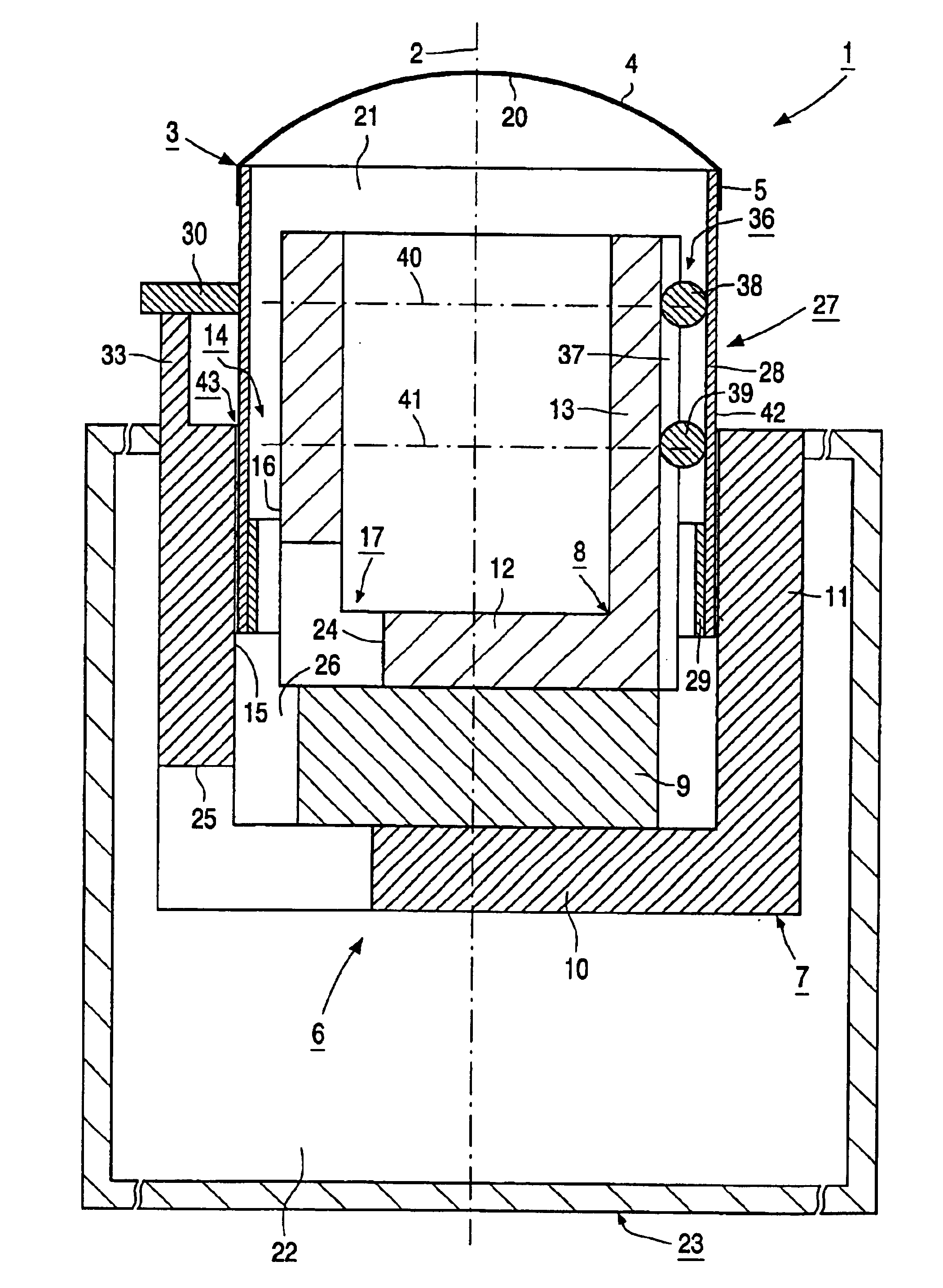
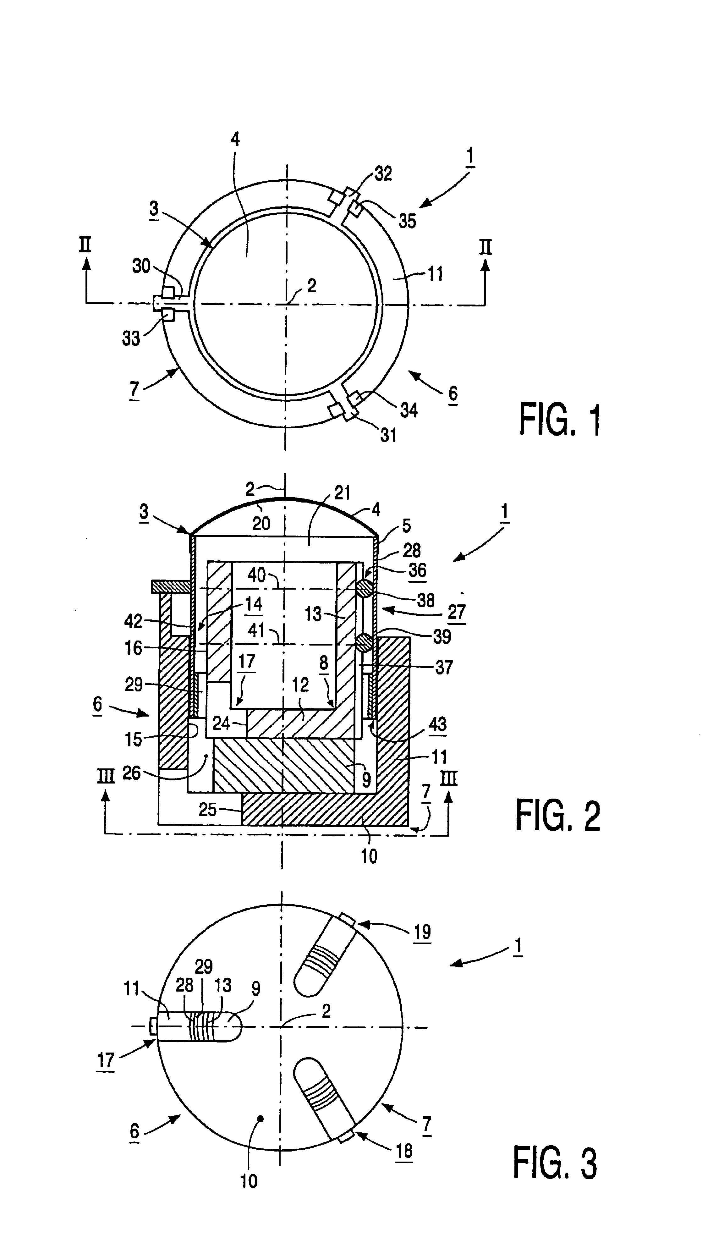
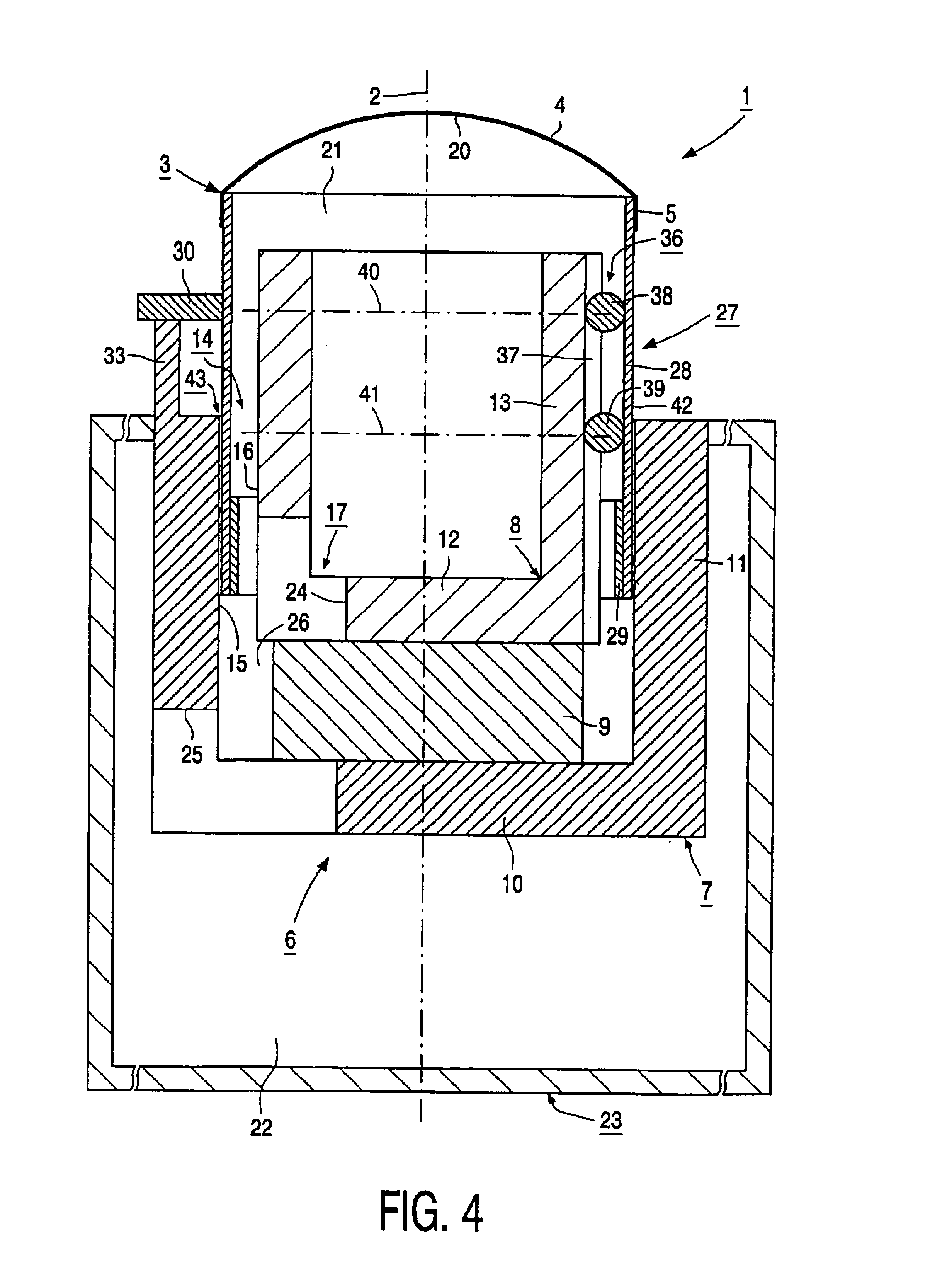
[0019]FIGS. 1 to 4 show an electroacoustic transducer 1. The electroacoustic transducer 1 in this case is an electrodynamic loudspeaker. The special features of this electrodynamic loudspeaker are that this speaker has small external dimensions, i.e., an overall external diameter in the range of around 20 to 25 mm, and that this speaker, despite its small size, has a particularly high reproduction quality, i.e., hi-fi reproduction quality, and that it is also achieved, with this speaker, that very low frequencies, which lie in the range between 20 and 50 Hz, can be reproduced by this speaker with an excellent quality.

[0020]The transducer 1 has a transducer axis 2 and is fitted with a membrane 3 capable of oscillation parallel to the transducer axis 2. The membrane 3 is mainly cup- or dome-like and has a cupor dome-like portion 4 and a hollow cylindrical fixing portion 5 projecting from the portion 4 parallel to the transducer axis 2.

[0021]The transducer 1 is also fitted with a magne...


PUM


Abstract

A transducer (1) includes a transducer axis (2), a membrane (3), a magnet system (6) having an outer magnet system part (7) and an inner magnet system part (8), a moving coil configuration (27) connected to the membrane (3) and having a coil carrier (28) and a moving coil (29) held by the coil carrier (28) in an air gap (14) between the two magnet system parts (7, 8), and guides (36) for rectilinearly guiding the moving coil configuration (27) parallel to the transducer axis (2). The moving coil configuration (27) has a cylindrical boundary surface (42) which, together with a cylindrical boundary surface (15) of the outer magnet system part (7), delimits a cylindrical gap (43) which is acoustically impermeable above a lower limit frequency of at most 100 Hz.

Description

BACKGROUND OF THE INVENTION[0001]1. Field of the Invention[0002]The invention relates to an electroacoustic transducer having a transducer axis and a membrane, a magnet system including an external magnet system part and an internal magnet system part together enclosing an air gap, a moving coil configuration connected to the membrane and having a coil carrier and a moving coil supported by the coil carrier and held in the air gap, and guide means for guiding the moving coil configuration rectilinearly parallel to the transducer axis.[0003]2. Description of the Related Art[0004]Such an electroacoustic transducer is known from U.K. Patent Specification No. GB 383,376. The hollow cylindrical moving coil in the known transducer lies opposite a cylindrical boundary surface of the outer magnet system part such that there is a relatively large space between the moving coil and the cylindrical boundary surface of the outer magnet system part (there is no information in this patent document...

Claims


Application Information

Patent Timeline
IPC IPC(8): H04R1/24H04R9/04H04R9/02H04R9/10
CPCH04R9/045H04R9/10H04R9/02
Inventor RENNER, HEINZ
Owner KONINKLIJKE PHILIPS ELECTRONICS NV
Why Eureka
Try Eureka