Motorized self-draining utility bucket

a self-draining, utility bucket technology, applied in the direction of liquid dispensing, special dispensing means, gymnasiums, etc., can solve the problem that none of them has a motorized drainage system that will push the wastewater, and achieve the effect of minimizing the chance of injury and destruction of assets, facilitating use of utility buckets, and minimizing the financial cost of maintenance operations

Inactive Publication Date: 2005-12-20
SANABRIA EDWIN
View PDF19 Cites 33 Cited by
  • Summary
  • Abstract
  • Description
  • Claims
  • Application Information

AI Technical Summary

Benefits of technology

[0026]Yet another object of the present invention is to provide ease of use of a utility bucket by eliminating the need to lift the bucket in order to drain wastewater into an above ground sink.
[0027]Still yet another object of the present invention is to equip the utility bucket at all times with a drain hose that has a hook-shaped drain head, with which to drain wastewater without having to lift the bucket.
[0028]Another object of the present invention is to equip the utility bucket with a clip-on fill hose at all times, with which to fill the bucket with tap water without having to lift the bucket.
[0029]Another object of the present invention is to minimize the chance of injury and destruction of assets that may ensue in the process of said lifting and manhandling of utility buckets.
[0030]Yet another object of the present invention is to minimize financial cost of maintenance operation in regard to insurance and replacement as well as downtime due to sick leaves.

Problems solved by technology

Troughs in the planar portion of the interior filter and corrugations in the floor of the bucket adjacent the filter recess trap detritus when the bucket is drained.
While most of these utility buckets provide adequate drainage of the wastewater toward the ground outlet below the bucket, none of them has a motorized drainage system that will push the wastewater up into a sink as hereinafter described.

Method used


Image

  • Motorized self-draining utility bucket
  • Motorized self-draining utility bucket
  • Motorized self-draining utility bucket

Examples


Embodiment Construction

[0076]The following discussion describes in detail one embodiment of the invention (and several variations of that embodiment). This discussion should not be construed, however, as limiting the invention to those particular embodiments, since practitioners skilled in the art will recognize numerous other embodiments as well. For a definition of the complete scope of the invention, the reader is directed to the appended claims.

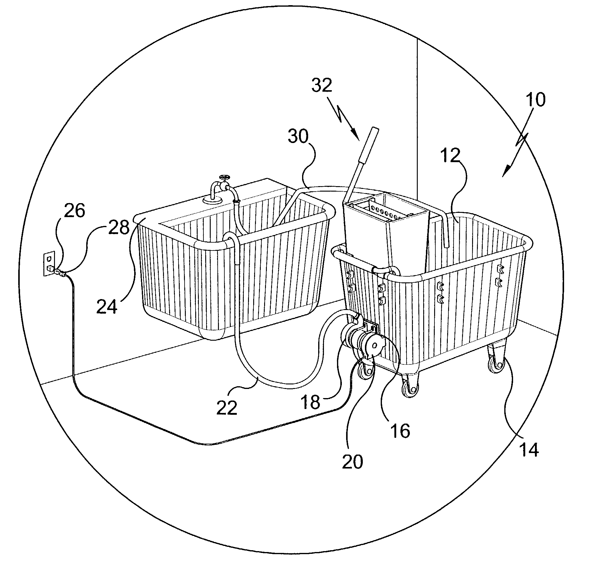
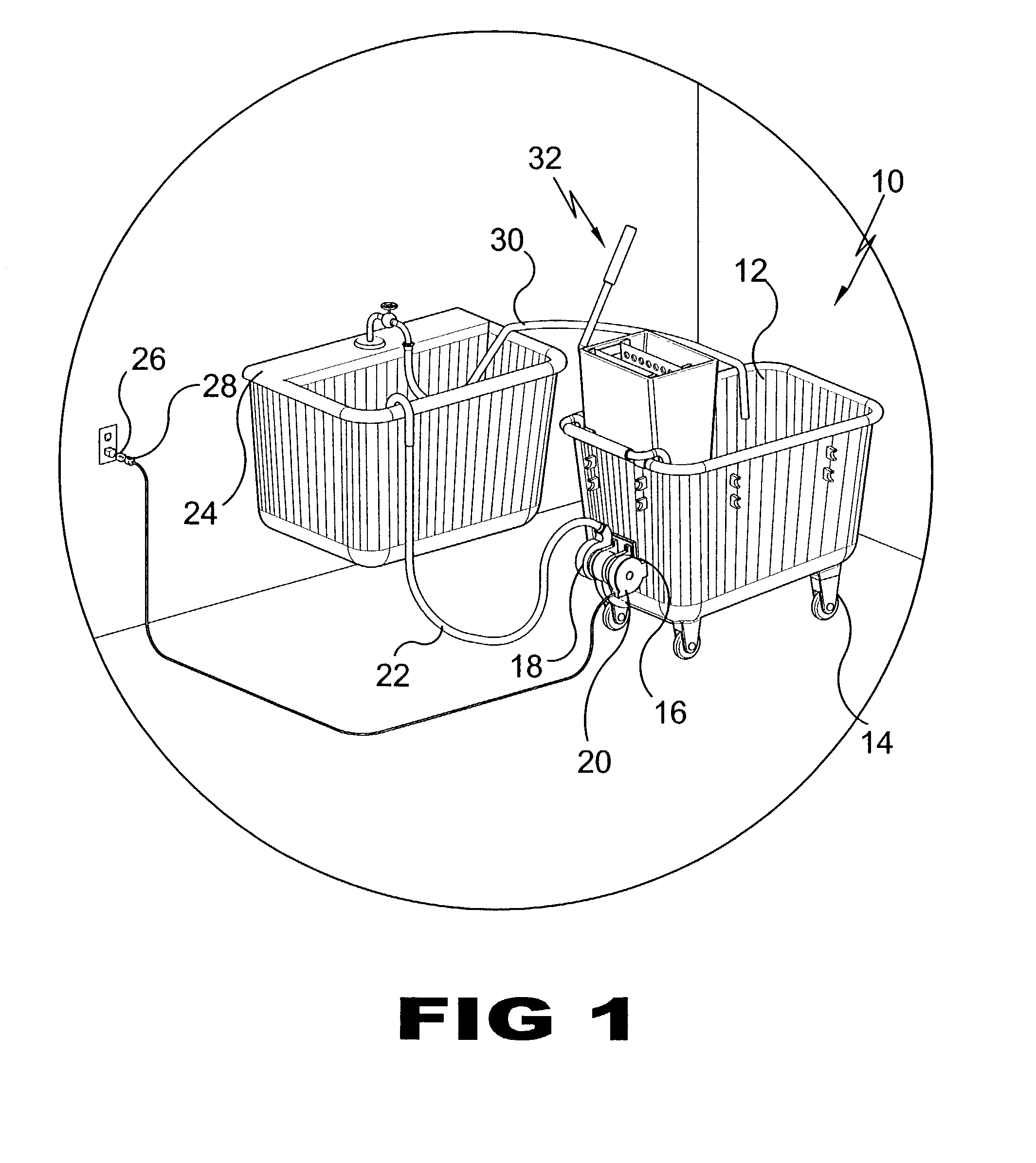
[0077]Turning to FIG. 1, shown therein is an illustrative view of the self-draining bucket of the present invention 10 in use. The motorized drainage system of the present invention 10 comprises a portable bucket 12 on wheels 14, a draining pump assembly 16 which incorporates an electrical motor 18 and a retractable power supply cord assembly 20. The wastewater from the bucket 12 is pumped upwardly through the drain hose 22 and dispensed into a sink 24. This eliminates any need to lift the bucket 12 in order to drain it, which saves pain and hard work, and, mor...


PUM

PropertyMeasurementUnit
areaaaaaaaaaaa
poweraaaaaaaaaa
forcesaaaaaaaaaa

Abstract

The present invention 10 discloses a portable, self-draining utility bucket 12. The motorized drainage system of the present invention 10 comprises a bucket 12 on wheels 14, a draining pump assembly 16 which incorporates an electrical motor 18 and a retractable cord assembly 20. The wastewater from the bucket 12 is pumped through the drain hose 22 and dispensed into a sink 24. This eliminates any need to lift the bucket 12 in order to drain it, which saves pain and hard work, and eliminates possible injury at work. An on/off switch 26, a ground fault interrupter circuit breaker (GFI) 28, a clip-on fill hose 30, and a conventional mop strainer 32 are also provided. The present invention has three designs for domestic, commercial and hospital applications.

Description

BACKGROUND OF THE INVENTION[0001]1. Field of the Invention[0002]The present invention relates generally to utility buckets and, more specifically, to motorized self-draining utility buckets.[0003]2. Description of the Prior Art[0004]All of the utility buckets found incorporate some sort of draining features. There are a few that forces draining. Typical of these is a U.S. Pat. No. 5,961,006 issued to Dunham, et al. on Oct. 5, 1999, which utilizes a manual pump assembly.[0005]Most utility buckets are gravity draining. A patent was issued on one such buckets to Don A. Smith on Mar. 20, 1990 as U.S. Pat. No. 4,908,904. Yet another U.S. Pat. No. 1,236,156 was issued to Walter. S. Finnell on Aug. 7, 1917 and still yet another was issued on Sep. 4, 2001 to Robert S. Robinson as U.S. Pat. No. 6,283,170.[0006]Another patent was issued to Hardesty, et al. on Apr. 1, 1997 as U.S. Pat. No. 5,615,447. Yet another U.S. Pat. No. 6,279,195 was issued to Blyth S. Biggs on Aug. 28, 2001. Another was...

Claims


Application Information

Patent Timeline
Patent Type & Authority Patents(United States)
IPC IPC(8): A47J47/18A47L13/50A47L13/58
CPCA47J47/18A47L13/58Y10T137/6921Y10T137/86035
Inventor SANABRIA, EDWIN
Owner SANABRIA EDWIN
Why Eureka
Try Eureka