
Combination wet suit and flotation device

a wet suit and flotation device technology, applied in life-saving, waterborne vessels, underwater equipment, etc., can solve the problems of affecting the wearability of personal flotation devices and dangerous situations, and achieve the effect of stable and dry position, ensuring safety, and ensuring user comfor

Inactive Publication Date: 2005-12-20
TURNER FRANKLIN A
View PDF11 Cites 27 Cited by
  • Summary
  • Abstract
  • Description
  • Claims
  • Application Information

AI Technical Summary

Benefits of technology

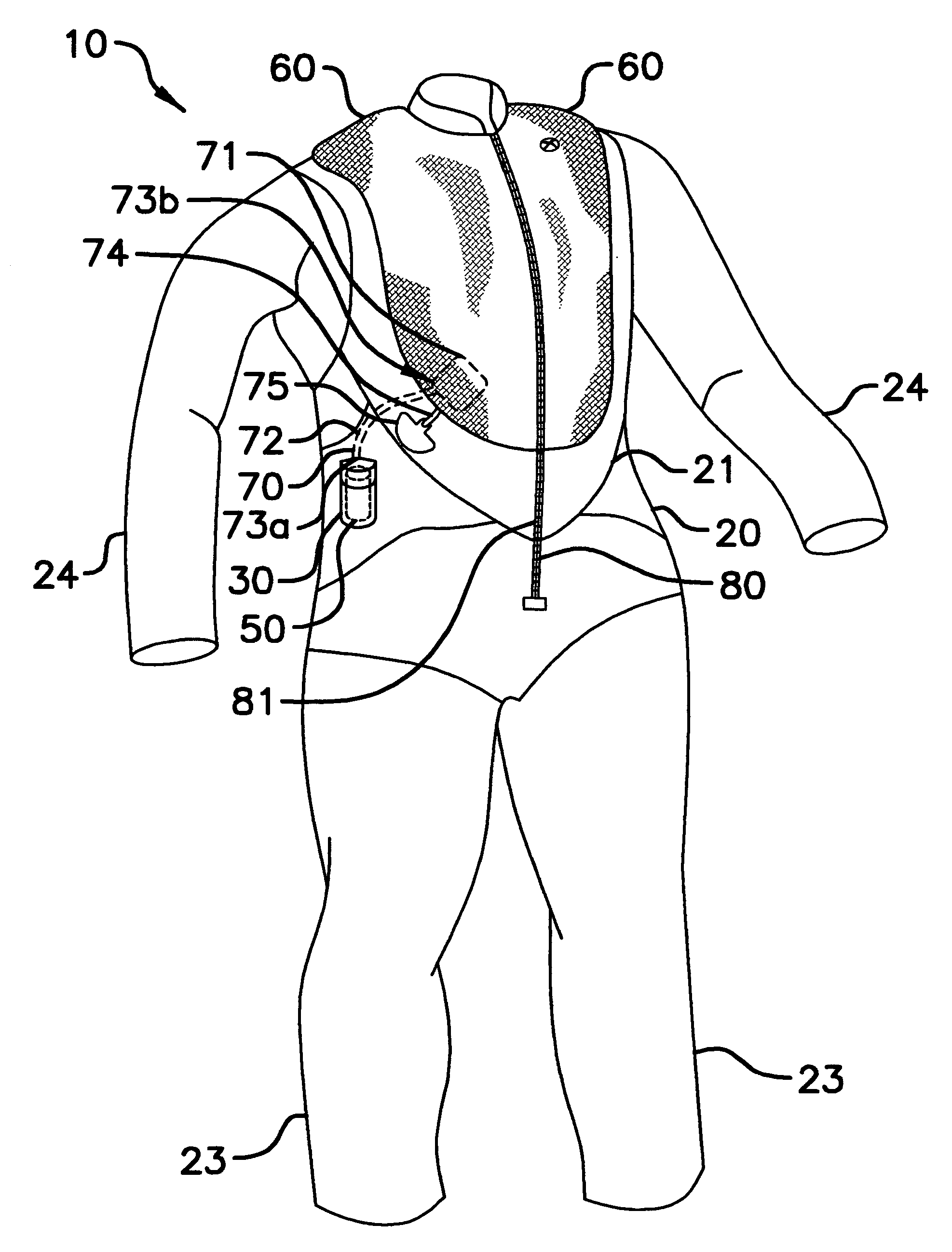
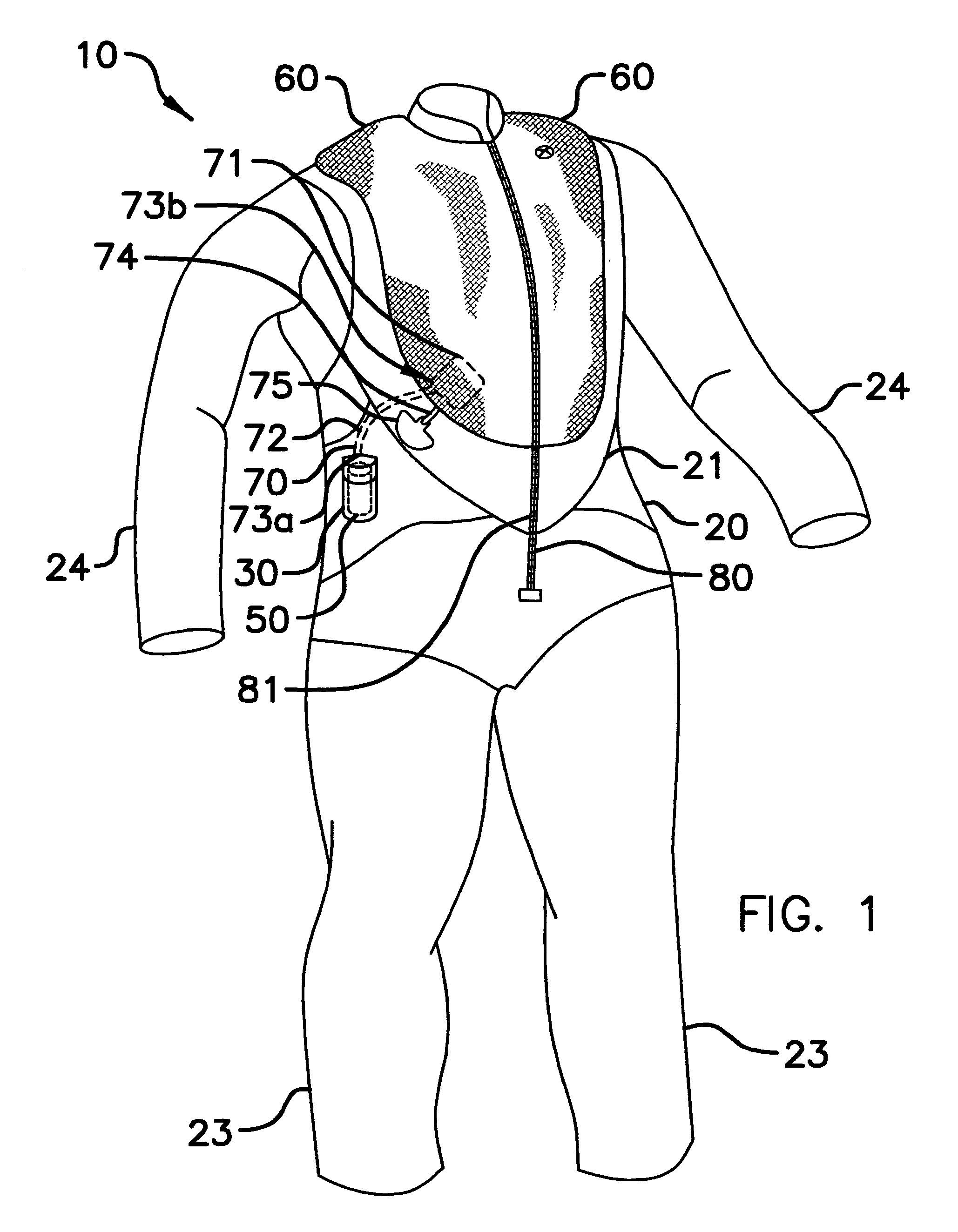
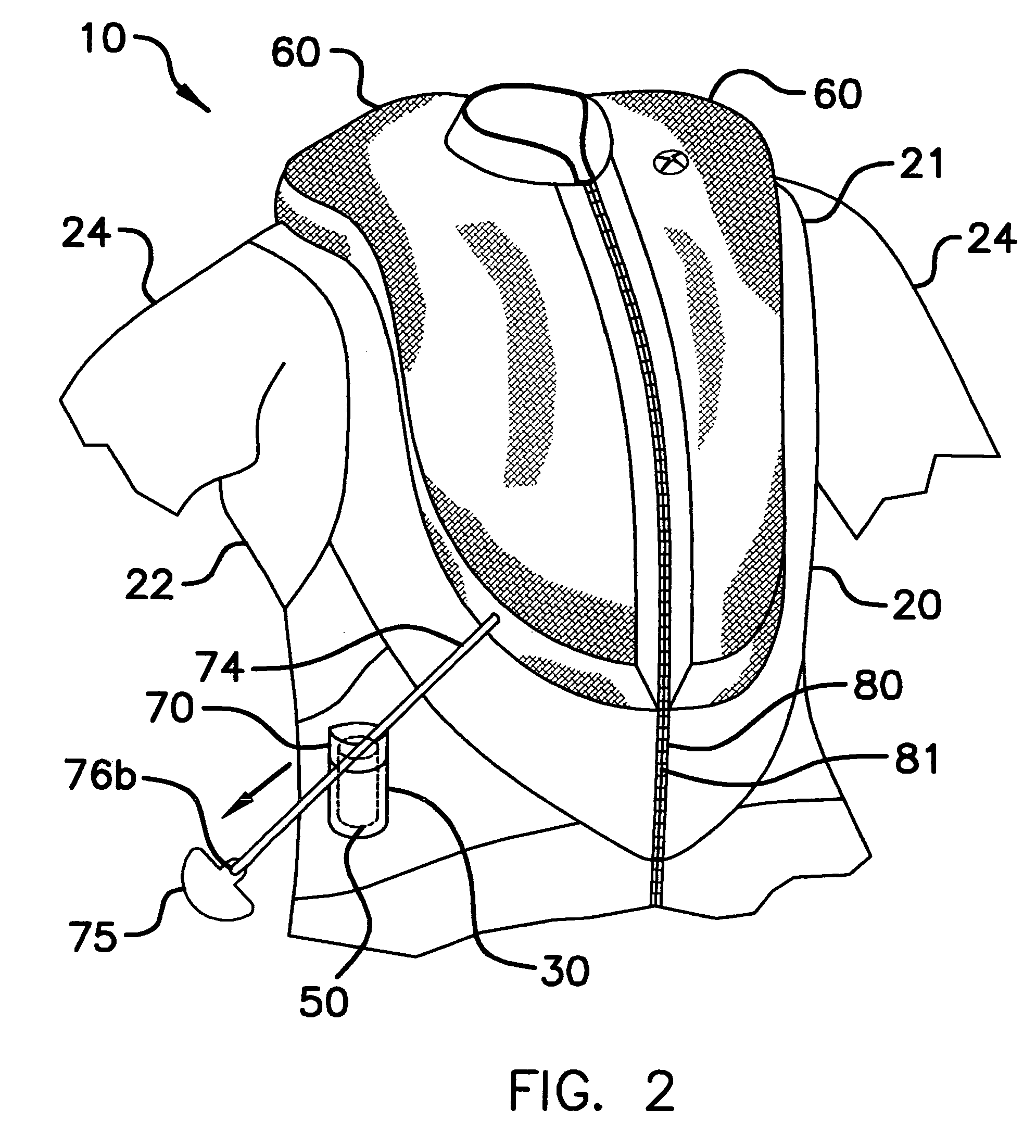
[0011]For example, the wet suit may be formed from flexible neoprene material for advantageously maintaining a user's body temperature at a safe level. Such a wet suit includes an upper torso section that has front and rear portions wherein the rear portion includes a pocket that has a flap movable between open and closed positions for maintaining a water-proof seal. Such a pocket includes a flexible retaining strap that has opposed end portions secured within the pocket and removably fastened thereto respectively. The strap advantageously secures objects thereto and assists a user to maintain the objects in a substantially stable and dry position. The wet suit further has a pair of leg and arm portions integral with the torso section and extending outwardly therefrom.
[0015]The inflating mechanism also includes a flexible pull cord including a handle for initiating the flow of CO2. The pull cord has opposed end portions secured to the valve and the handle respectively. The handle assists a user to selectively pull the cord and open the valve for advantageously inflating the bladder wherein the bladder is caused to expand as CO2 flows out of the canister and into the bladder.

Problems solved by technology

These vests, however, are not suitable to be worn by individuals that are performing activities such as diving or surfing which requires constant and free range of movement, and thus leaves them in a dangerous situation when staying above water becomes a problem.
In addition, the wearability of the personal flotation device is affected by the buoyancy of the personal flotation device.

Method used


Image

  • Combination wet suit and flotation device
  • Combination wet suit and flotation device
  • Combination wet suit and flotation device

Examples


Embodiment Construction

[0025]The present invention will now be described more fully hereinafter with reference to the accompanying drawings, in which a preferred embodiment of the invention is shown. This invention may, however, be embodied in many different forms and should not be construed as limited to the embodiment set forth herein. Rather, this embodiment is provided so that this application will be thorough and complete, and will fully convey the true scope of the invention to those skilled in the art. Like numbers refer to like elements throughout the figures.

[0026]The device of this invention is referred to generally in FIGS. 1–7 by the reference numeral 10 and is intended to provide a combination wet suit and flotation device. It should be understood that the device 10 may be used to inflate many different objects and should not be limited to only wet suits.

[0027]Referring initially to FIG. 1, the device 10 includes an upper torso section 20 that has front 21 and rear 22 portions wherein the rea...


PUM


Abstract

The present invention advantageously provides a combination wet suit and flotation device integral with the wet suit so that a user can maintain unrestricted movement during water-sport activities, which improves convenience and comfort. A wet suit worn by water-sport a participant includes a torso section having a pocket provided with a movable flap and a waterproof seal. A CO2 canister is housing with the pocket and includes a strap positioned thereabout for securing the canister during operating conditions. A pull cord is connected to the canister and associated valve for actuating the flow of CO2 into a bladder defined adjacent the torso section of the wet suit. In operation, when a user pulls the cord, the canister inflates the bladder for assisting to maintain a user's head above the water line.

Description

CROSS REFERENCE TO RELATED APPLICATIONS[0001]Not Applicable.STATEMENT REGARDING FEDERALLY SPONSORED RESEARCH OR DEVELOPMENT[0002]Not Applicable.REFERENCE TO A MICROFICHE APPENDIX[0003]Not Applicable.BACKGROUND OF THE INVENTION[0004]1. Technical Field[0005]This invention relates to a wet suit and, more particularly, to a combination wet suit and flotation device including an actuator for inflating a bladder integral with the wet suit so that a user's head can be maintained above a water line during emergency conditions.[0006]2. Prior Art[0007]There are many different types of personal flotation devices currently in use by water sport enthusiasts. In particular, a personal flotation device such as a Coast Guard Type III life vest is popular. These life vests are designed for use in calm inland waters where there is a good chance of fast rescue. These vests, however, are not suitable to be worn by individuals that are performing activities such as diving or surfing which requires const...

Claims


Application Information

Patent Timeline
IPC IPC(8): B63C9/08B63C9/087B63C9/105
CPCB63C9/087B63C9/1055
Inventor TURNER, FRANKLIN A.
Owner TURNER FRANKLIN A
Learn More