Retainer sleeve for transmission gear axle

a technology for transmission gear axles and retainers, which is applied in the direction of differential gearings, belts/chains/gearrings, and differential gearings. it can solve the problems of increasing exacerbate the damage caused, and increase the number of transmissions. it increases the expense of the vehicle owner

Inactive Publication Date: 2005-12-20
BONANTI WILLIAM J
View PDF10 Cites 7 Cited by
  • Summary
  • Abstract
  • Description
  • Claims
  • Application Information

AI Technical Summary

Benefits of technology

[0002]A number of transmissions suffer from a common problem. An axle for a pair of spider gears is retained in place in the differential carrier by a fragile pin. This pin frequently breaks or otherwise becomes disengaged allowing the axle to axially slide out of its housed position in the differential carrier. This often happens when the differential carrier is turning at speeds upwards of 5000 rpm. This will launch this axle at high velocity, impacting the transmission housing and knocking a hole in the wall of this cast aluminum part. This greatly exacerbates the damage caused by the axle being let loose and multiplies the expense to the vehicle's owner. This missile and the shrapnel it creates can do additional damage to the vehicle, as well as pose a safety threat to the passengers of the car or truck.
[0003]While a number of transmissions have this problem, the particular transmission for which the retainer ring of the present invention has been designed is the 604 trans-axle, a transmission used on most all Chrysler minivans since 1988. In a transmission housing in which a fragile pin serves as retention means for an axle for one or more spider gears in a differential carrier, the present invention comprises a sleeve which encircles the differential carrier at a point in which the axle is mounted for rotation in the differential carrier; means to attach said sleeve to a ring of a ring and pinion of the differential carrier; whereby when the fragile pin breaks, said sleeve retains the axle within the differential carrier preventing the axle from damaging the transmission housing.

Problems solved by technology

A number of transmissions suffer from a common problem.
This will launch this axle at high velocity, impacting the transmission housing and knocking a hole in the wall of this cast aluminum part.
This greatly exacerbates the damage caused by the axle being let loose and multiplies the expense to the vehicle's owner.
This missile and the shrapnel it creates can do additional damage to the vehicle, as well as pose a safety threat to the passengers of the car or truck.

Method used


Image

  • Retainer sleeve for transmission gear axle
  • Retainer sleeve for transmission gear axle
  • Retainer sleeve for transmission gear axle

Examples


Embodiment Construction

)

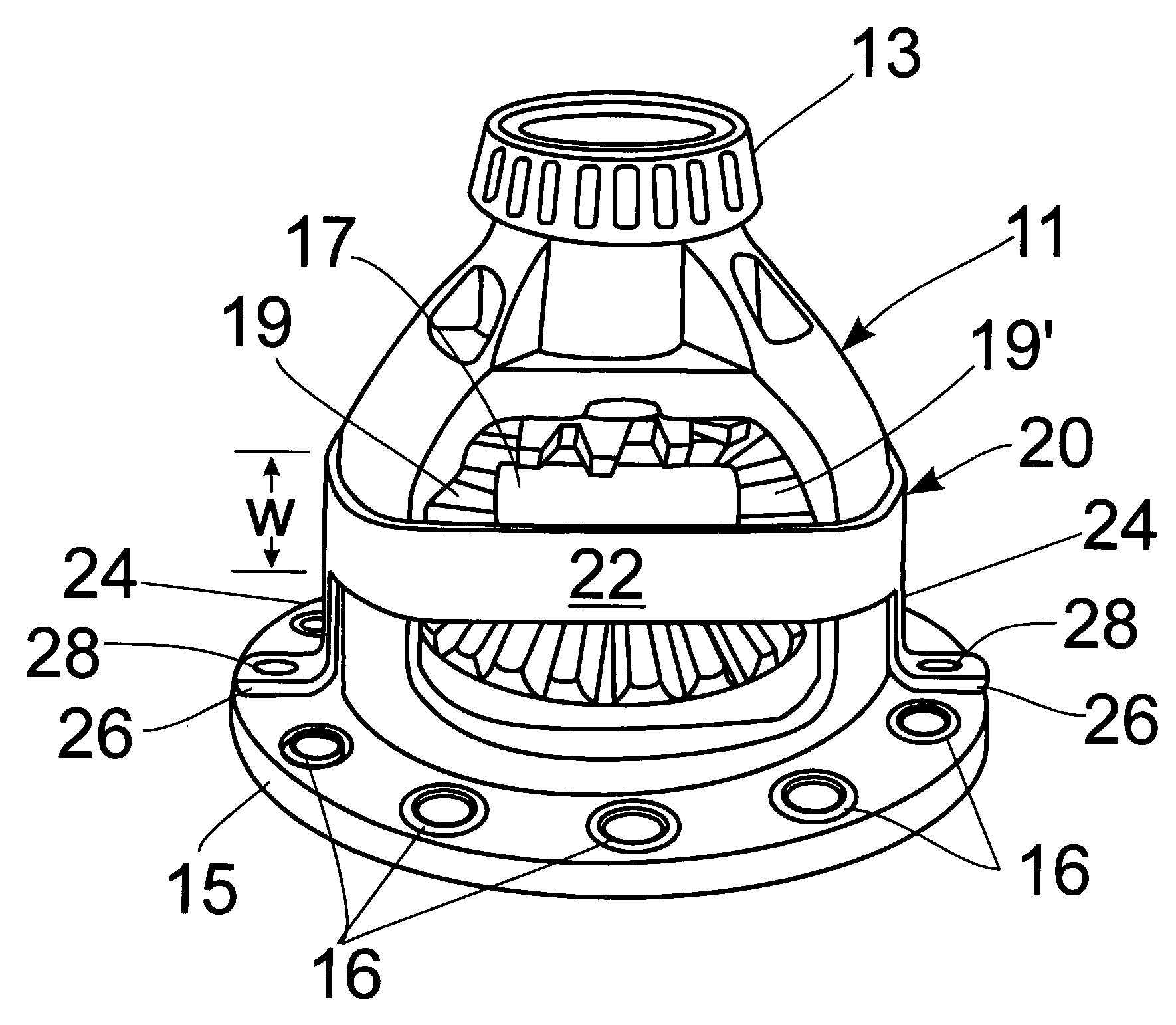
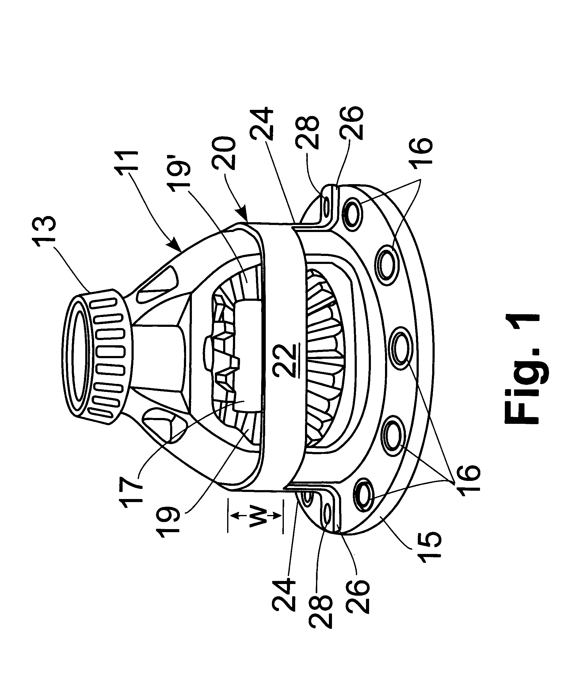
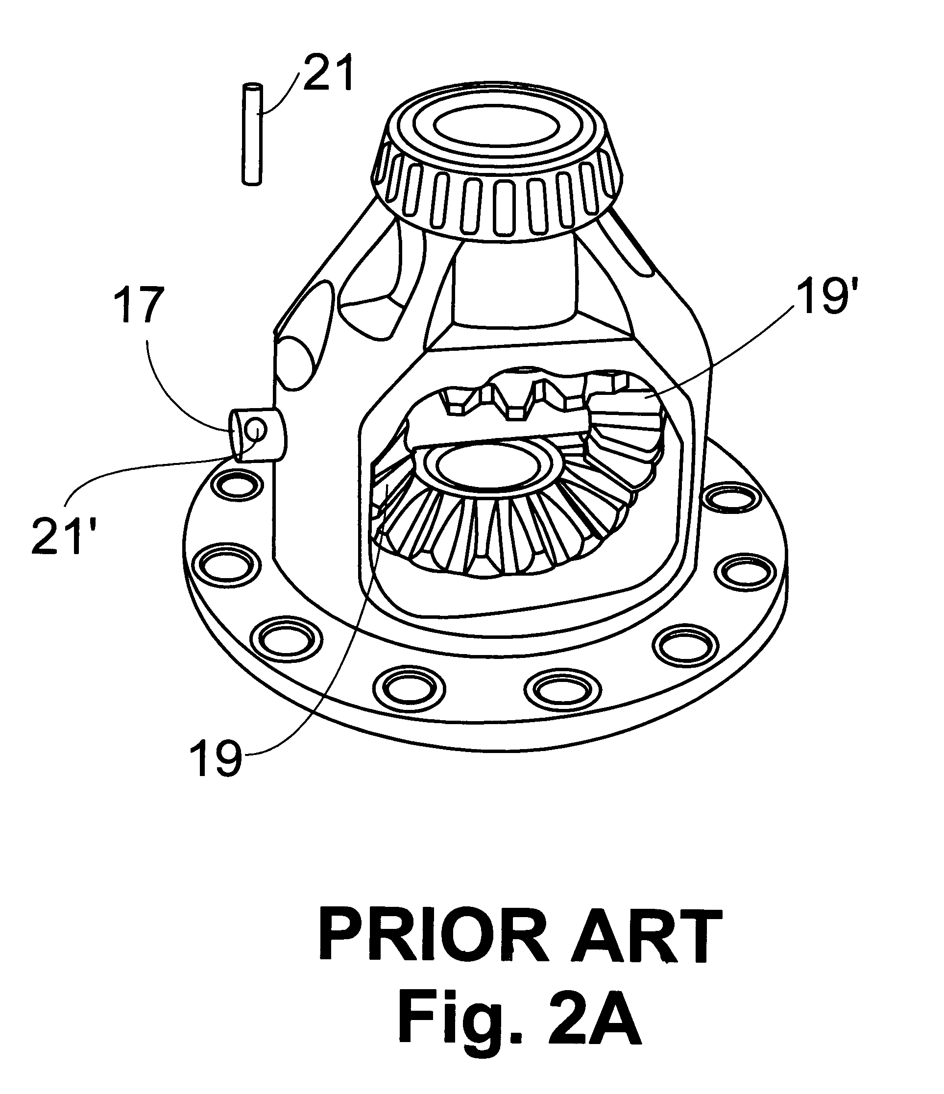
[0012]The retainer sleeve of the present invention is shown in FIGS. 1, 3, 4 generally at 20. As best seen in FIG. 2A, the differential carrier 11 has a bearing 13 on its upper end and a laterally extending flange 15 on its lower end with bores 16 there through by which it is bolted to the ring of a ring and pinion gear (not shown). Axle 17 mounts two spider gears 19, 19′ and is retained in place by pin 21 press fit in hole 21′ (FIG. 2A). This pin 21 has a tendency to break or otherwise become disengaged as the transmission undergoes typical wear and tear. With the pin 21 missing, axle 17 becomes a missile launched at high rpm that can rip a hole in the transmission housing 23 (FIG. 2B). As seen in FIG. 2B, hole 25 in the transmission housing 23 is indicative of the type of damage that can result. Replacement of the housing 23 is the only viable option which significantly increases the cost of the repair.

[0013]The retainer sleeve comprises an annulus or ring 22 having a width ‘w’ a...


PUM


Abstract

A retainer sleeve surrounds a differential carrier in line with an axle for the two laterally positioned spider gears preventing the axle from slipping out of its mounting in the differential carrier and tearing a hole in the transmission housing. The sleeve is an annulus that has a pair of legs extending from one edge thereof, each leg have a foot with a hole there through which overlies one of the bores in the flange of the differential carrier by which it is attached to the ring of the ring and pinion gear.

Description

BACKGROUND AND SUMMARY OF THE INVENTION[0001]The present invention is directed to vehicle transmissions. More particularly, the present invention is directed to a retainer sleeve which surrounds a differential carrier inside the transmission housing which keeps the axle for two of the spider gears from blowing a hole in the housing should the retention pin break, or otherwise become disengaged, from the axle.[0002]A number of transmissions suffer from a common problem. An axle for a pair of spider gears is retained in place in the differential carrier by a fragile pin. This pin frequently breaks or otherwise becomes disengaged allowing the axle to axially slide out of its housed position in the differential carrier. This often happens when the differential carrier is turning at speeds upwards of 5000 rpm. This will launch this axle at high velocity, impacting the transmission housing and knocking a hole in the wall of this cast aluminum part. This greatly exacerbates the damage caus...

Claims


Application Information

Patent Timeline
Patent Type & Authority Patents(United States)
IPC IPC(8): F16H48/06F16H48/08
CPCF16H48/08F16H48/40
Inventor BONANTI, WILLIAM J.
Owner BONANTI WILLIAM J
Why Eureka
Try Eureka