Braided strainer for a draw line

a strainer and draw line technology, applied in the field of strainers, can solve the problems of reducing the efficiency of the draw line, reducing the efficiency of the strainer, and consuming a lot of resources, and achieve the effect of simple and economical construction

Inactive Publication Date: 2005-12-27
DEPENDABLE TRUCK & TANK
View PDF8 Cites 4 Cited by
  • Summary
  • Abstract
  • Description
  • Claims
  • Application Information

AI Technical Summary

Benefits of technology

[0009]The strainer according to the present invention is relatively simple and economical to construct. Because of the braided wall construction of the strainer.

Problems solved by technology

The construction proposed by Avery et al. presents difficulties in that a woven material may be prone to tearing or dislocation of certain of the strands of strainer medium, making the strainer less effective.
As well, constructing such a strainer, by weaving the fabric, is a laborious and time consuming process, resulting in a relatively expensive product.
Problems encountered with perforated sheets of specified orifice or openings include the creation of vortexes which, reduce the efficiency of the draw line.

Method used


Image

  • Braided strainer for a draw line
  • Braided strainer for a draw line
  • Braided strainer for a draw line

Examples


Embodiment Construction

[0022]In the following description, similar features in the drawings have been given similar reference numerals.

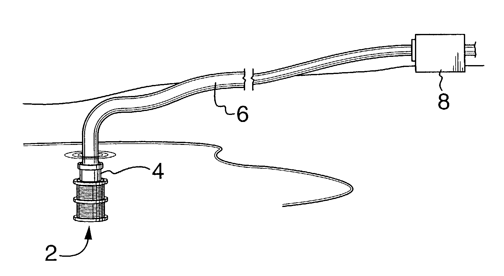
[0023]Turning to FIG. 1 there is illustrated a strainer (2) in accordance with the present invention, secured by appropriate connection means (4) such as a bolted flange (illustrated), or (not illustrated) a hose shank connector, cam lock connection, storks connection, threaded swivel connection or the like, to a mating connector on draw line (6) to join strainer (2) to draw line (6). The strainer as illustrated is immersed in a pond and is intended to strain coarse debris which otherwise would become entrained in the draw line water as it is pumped through action of pump (8). The connector (4) is intended to provide for an unlimited number of quick detachable or standard threaded connectors. Some connections may allow the strainer (2) to rotate or pivot without disturbing the draw line.

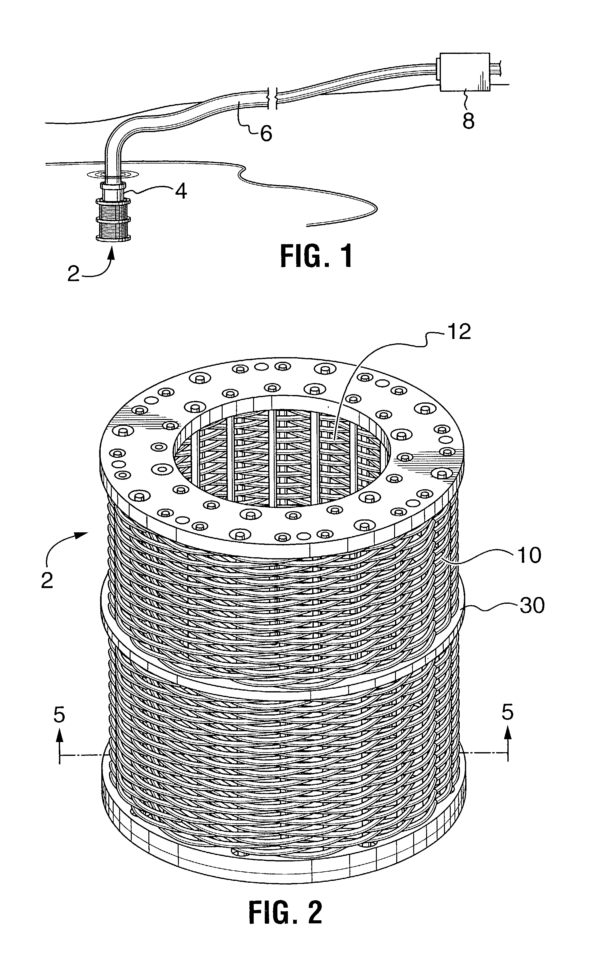
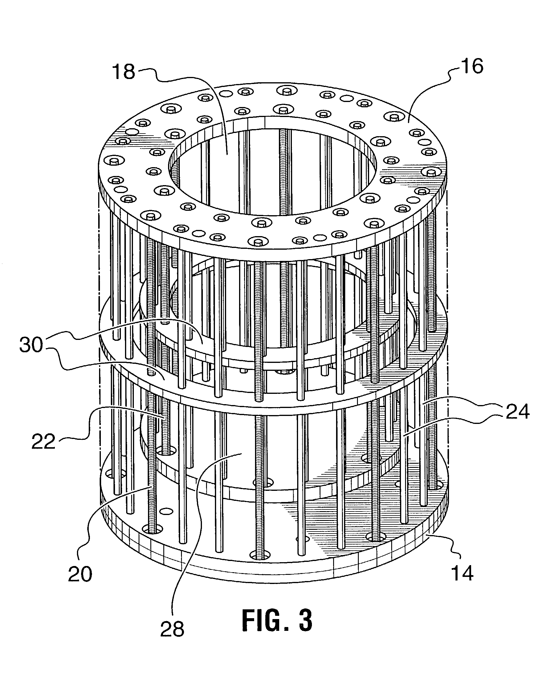
[0024]An example embodiment of strainer (2) is illustrated in FIGS. 2 to 5. In this emb...


PUM

PropertyMeasurementUnit
diameteraaaaaaaaaa
diameteraaaaaaaaaa
lengthaaaaaaaaaa

Abstract

A braided strainer for a draw line, and method of forming same. The strainer comprises a frame in the form of a pair of spaced planar plates, one being a solid end plate and the other having a control aperture. A plurality of spaced, parallel rods of similar length are positioned near the peripheries of the plates and secured and extending between the plates. A plurality of cylindrical walls of braided strands of strainer medium, are provided, the braided cylindrical walls having similarly spaced rod-receiving holes extending longitudinally in spaced fashion through the strands of strainer medium. These walls are contiguously stacked on the plates to extend between them. The plate having the central aperture permits flow of fluid drawn through the cylindrical walls during operation of the strainer. That plate has associated with it a connector to releasably secure the strainer to a mating connector on a free end of the draw line.

Description

FIELD OF THE INVENTION[0001]The present invention relates to a strainer for filtering coarse debris from a fluid or from solids, the strainer usable for example with fire truck hoses for drawing water from rivers, lakes or ponds.BACKGROUND OF THE INVENTION[0002]Generally, when such strainers are used in a fluid, the strainer assembly is submerged into the fluid and always must have a means of connecting to a hose, piping or to a fixture, hereinafter called a “draw line”. Strainers generally use a strainer medium formed from perforated sheets of specified orifice or openings or, as in the case of Avery et al. U.K. Patent No. 2,318,305, from a woven strands of material. The construction proposed by Avery et al. presents difficulties in that a woven material may be prone to tearing or dislocation of certain of the strands of strainer medium, making the strainer less effective. As well, constructing such a strainer, by weaving the fabric, is a laborious and time consuming process, resul...

Claims


Application Information

Patent Timeline
Patent Type & Authority Patents(United States)
IPC IPC(8): B01D29/11B01D35/02
CPCB01D29/111B01D35/02B01D29/114B01D29/48Y10T29/49602Y10T29/49604Y10S29/905
Inventor NATALE, SANTO
Owner DEPENDABLE TRUCK & TANK
Why Eureka
Try Eureka