Hydrostatic positive displacement machine

a positive displacement, machine technology, applied in the direction of positive displacement liquid engines, pumps, multi-cylinder pumps, etc., can solve the problems of increasing the number of components and thus the construction effort, occupying a great deal of construction space, and high cost of components, so as to achieve the effect of easy machined, and little extra manufacturing effort and expens

Inactive Publication Date: 2017-02-07
LINDE HYDRAULICS
View PDF16 Cites 1 Cited by
  • Summary
  • Abstract
  • Description
  • Claims
  • Application Information

AI Technical Summary

Benefits of technology

[0012]The invention accomplishes this object in that the setting valve means of the position-controlled control valve are axially displaceable and non-rotatable, and the feedback valve means of the position-controlled control valve are rotatable and locked to prevent axial displacement. As the result of an axial displacement of the setting valve means relative to the feedback valve means, control cross sections are exposed to pressurize a first positioning piston compression chamber of the positioning piston device with a control pressure and to decompress a second positioning piston compression chamber of the positioning piston device to a reservoir. The control cross sections are closed by a rotational movement of the feedback valve means relative to the setting valve means. The control valve of the invention therefore has non-rotatable and axially longitudinally displaceable setting valve means to specify the pivot angle control value. A setting valve means of this type can be easily actuated by a hydraulic actuator pressure. The current position of the pivoting cradle is fed back to the rotational feedback valve means, which are rotatable but are secured to prevent axial movement. Rotatable feedback valve means of this type can easily be coupled directly with the pivoting cradle. The position-controlled control valve of the invention therefore has only a small number of components and does not require a rotary lever or a complex mechanical coupling of the pivoting cradle and the feedback valve means, so that the positioning device of the invention is simple and economical to construct and can be very compact on account of the elimination of components.
[0013]On a position-controlled control valve of this type, the positioning piston compression chambers of the positioning piston device can be easily pressurized by a control pressure or decompressed to a reservoir if, as in one advantageous embodiment of the invention, helical control grooves are provided to form the control cross sections and are provided with control orifices that interact with the control grooves. With helical control grooves of this type and control orifices that interact with the control grooves and are located between the setting valve means and the feedback valve means, it becomes possible with little construction effort and expense, to expose control cross sections between the helical control grooves and the control orifices by the axial displacement of the setting valve means relative to the feedback valve means and to close the exposed control cross sections again by the rotational movement of the feedback valve means relative to the setting valve means.
[0014]It is particularly advantageous if, as in one development of the invention, the helical control grooves are inclined with respect to a longitudinal axis of the control valve. With an inclined orientation of the control grooves, it becomes easily possible during the axial displacement of the setting valve means relative to the feedback valve means to expose control cross sections on the control orifices and to close these cross sections again by the rotational movement of the feedback valve means relative to the setting valve means.

Problems solved by technology

Because of the requirement for a rotary lever, however, a position-controlled control valve in the form of a longitudinal slide valve member entails a high cost for components and thus a great deal of construction effort.
If the rotary lever is actuated to set the pivot angle control value of a hydraulically pressurized slave cylinder, the number of components and thus the construction effort increases even further, not to mention the fact that the positioning device occupies a great deal of construction space.
However, wear can occur between the groove in the sleeve and the component that is connected with the pivoting cradle, which has an adverse effect on the accuracy of the positioning.
However, on account of the presence of the rotary control slide valve member of a position-controlled control valve of this type (in the form of a rotary slide valve), in which the pivot angle control value is set by a rotational actuation of the control slide valve, it is not possible to actuate the rotary slide valve by a hydraulic actuator pressure generated by electrically actuated control pressure valves instead of by the stepper motor.

Method used


Image

  • Hydrostatic positive displacement machine
  • Hydrostatic positive displacement machine
  • Hydrostatic positive displacement machine

Examples


Embodiment Construction

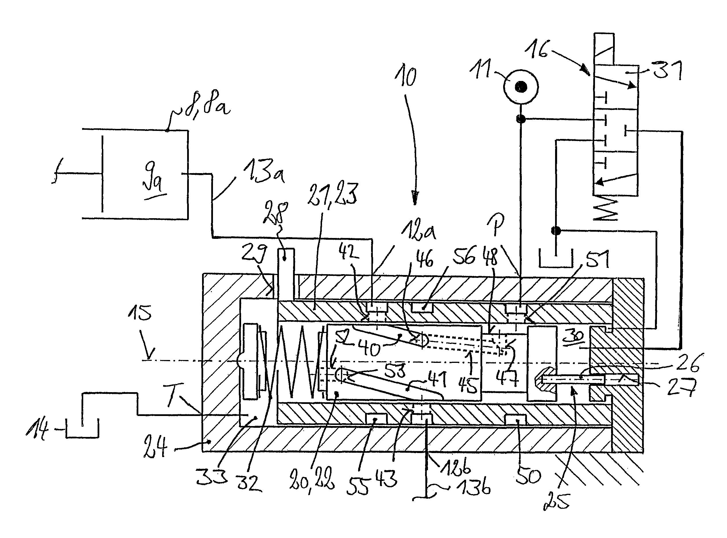
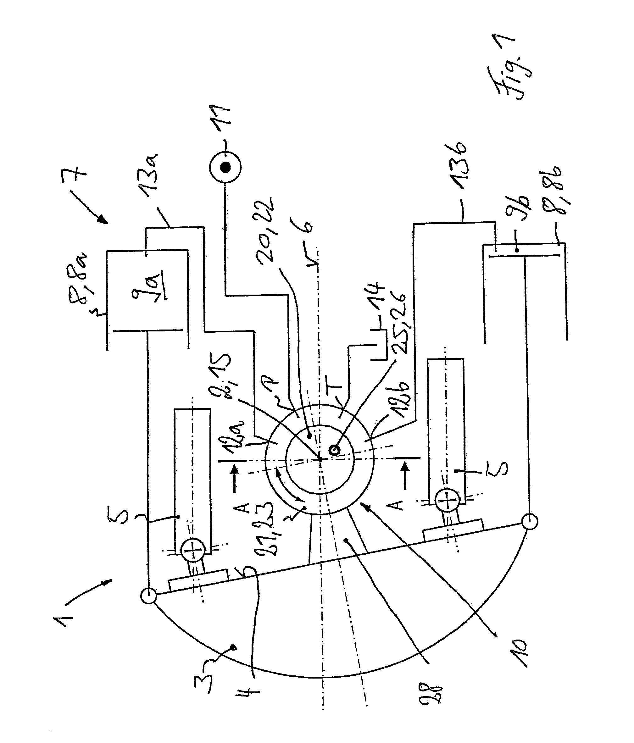
[0055]FIG. 1 shows a schematic longitudinal section of a positive displacement machine 1 in the form of an axial piston machine. The positive displacement machine 1 is in the form of a variable displacement machine with a variable displacement volume. To vary and set the positive displacement, the positive displacement machine 1 has a pivoting cradle 3 which pivots around a pivot axis 2. A swash plate 4 is formed on the pivoting cradle 3. Displacement pistons 5 of the positive displacement machine are supported on the swash plate 4. The displacement pistons 5 are arranged so that they move longitudinally in a cylinder drum, which is not illustrated in any further detail. In operation, the cylinder drum provided with the displacement pistons 5 rotates around an axis of rotation 6 which is oriented perpendicular to the pivoting axis 2 of the pivoting cradle 3 and forms a longitudinal axis of the positive displacement machine 1.

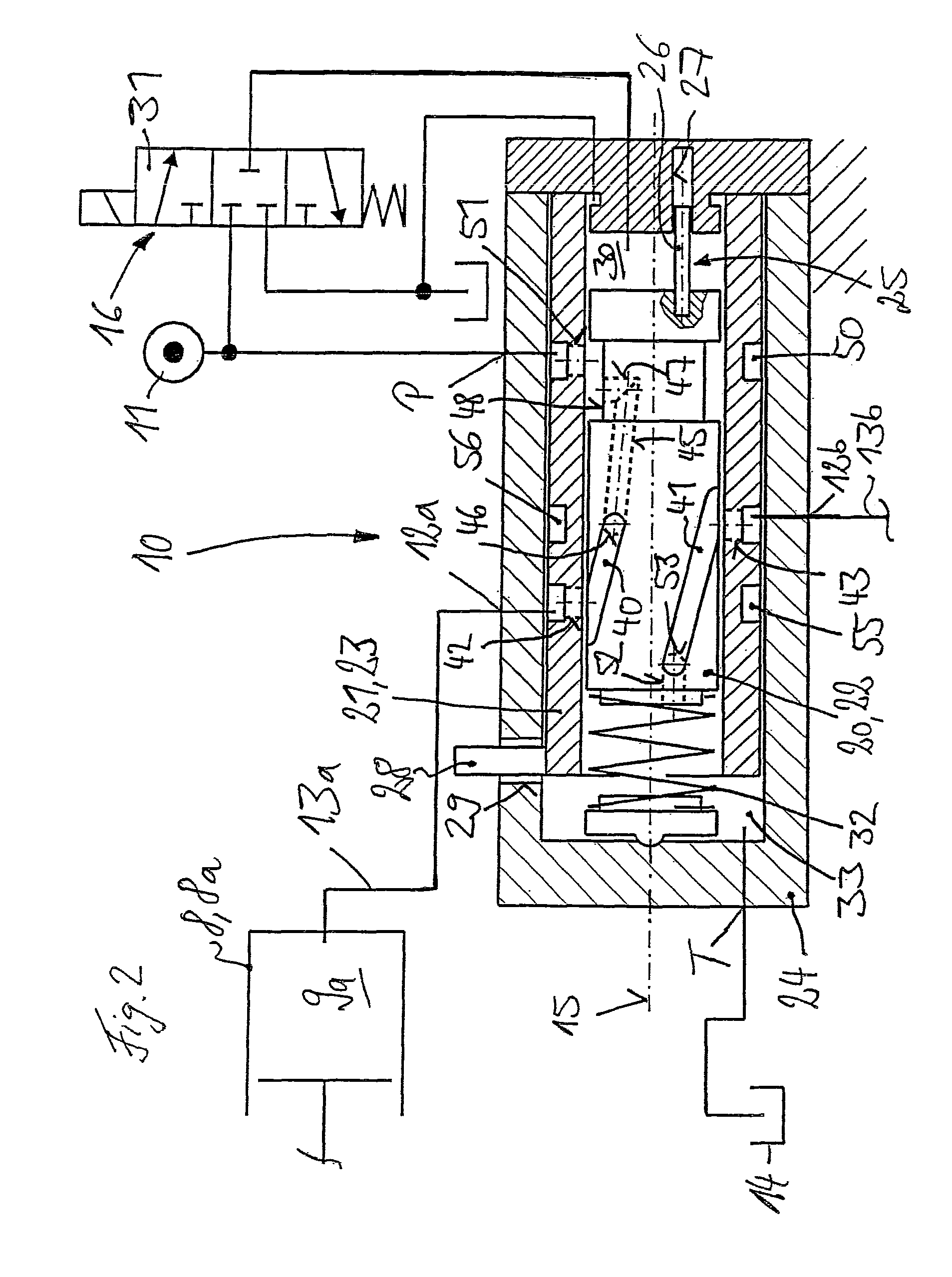
[0056]For pivoting of the pivoting cradle 3 around the piv...


PUM


Abstract

A hydrostatic positive displacement machine (1) with a variable displacement volume includes a cradle (3) pivoted by a hydraulic positioning device (7) having a positioning piston device (8). A position-controlled control valve (10) generates a control pressure and includes axially displaceable and locked setting valve means (20) and the rotatable feedback valve means (21). Control cross sections are exposed by an axial displacement of the setting valve means (20) relative to the feedback valve means (21) and are closed by rotational movement of the feedback valve means (21) relative to the setting valve means (20).

Description

CROSS REFERENCE TO RELATED APPLICATION[0001]This application claims priority to German Application DE 10 2012 106906.9 filed Jul. 30, 2012, which is herein incorporated by reference in its entirety.BACKGROUND OF THE INVENTION[0002]Field of the Invention[0003]The invention relates to a hydrostatic positive displacement machine, in particular an axial piston machine with a variable displacement, which to vary the displacement has a pivoting cradle that can be pivoted by a hydraulic positioning device around a pivot axis. The positioning device for pivoting the cradle around the pivot axis has a positioning piston device and, to generate a control pressure that acts on the positioning piston device, has a position-controlled control valve which, to set a pivot angle control value of the pivoting cradle, has setting valve means which are actuated by a setpoint device and comprise feedback valve means which are mechanically coupled with the pivoting cradle for feedback of the current piv...

Claims


Application Information

Patent Timeline
Patent Type & Authority Patents(United States)
IPC IPC(8): F16H61/42F04B1/20F04B1/30F04B1/32
CPCF16H61/42F04B1/2078F04B1/30F04B1/324F04B1/328
Inventor KRITTIAN, LUKAS
Owner LINDE HYDRAULICS
Why Eureka
Try Eureka