Aerosol spray container with time delayed release actuator

a technology of time-delay release and spray container, which is applied in the direction of transportation and packaging, combustion types, lighting and heating apparatus, etc., to achieve the effects of simple structure, reduced production cost and reduced production cos

Inactive Publication Date: 2005-12-27
JIN XIANYANG
View PDF5 Cites 45 Cited by
  • Summary
  • Abstract
  • Description
  • Claims
  • Application Information

AI Technical Summary

Benefits of technology

[0004]An object of the present invention is to provide an aerosol spray container with time delayed release actuator, by which the aerosol can be delayed to release, and what's more, the time delayed can be controlled.
[0011]The principle used in the present invention is that the flow velocity of the liquid differs under different damping situation. Therefore, the performance of the controllable damping also makes the delayed time controllable. Therefore, the aerosol spray container according to present invention can perform the delayed total release of the aerosol by its simple structure and with its low price.

Problems solved by technology

However, when using the aerosol spray container, the user has to rush out of the room in a hurry as soon as the valve means is pressed down so as to avoid breathing the spray in the air, especially when the aerosol has unpleasant odors.

Method used


Image

  • Aerosol spray container with time delayed release actuator
  • Aerosol spray container with time delayed release actuator
  • Aerosol spray container with time delayed release actuator

Examples


Embodiment Construction

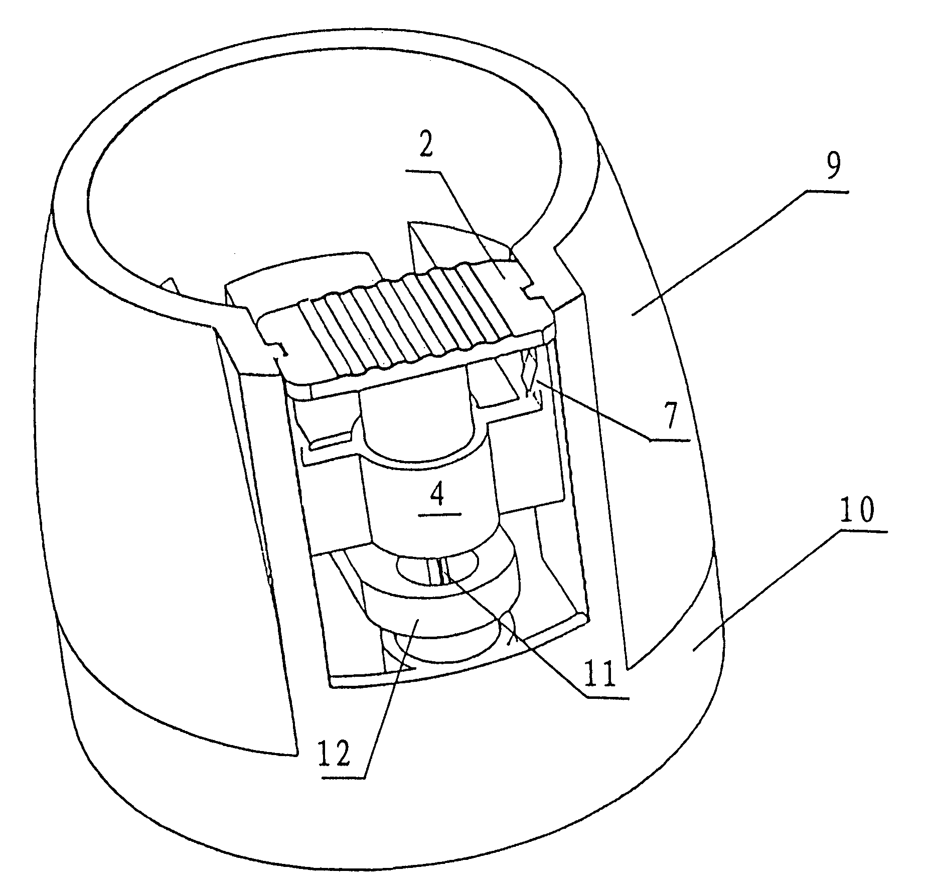
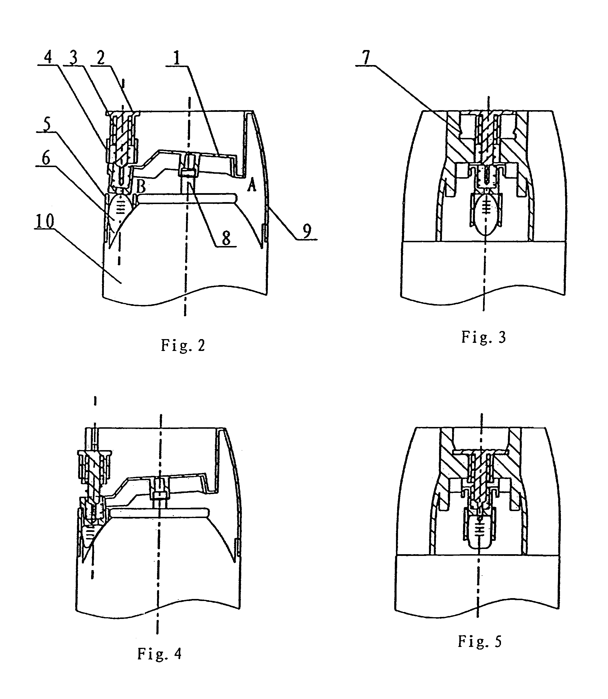
[0020]Reference will now be made to the drawings to describe the present invention in details. In each drawing, only the top part of the container is shown since a container main body is usually in common design.

[0021]As shown in FIG. 1 and FIG. 2, the aerosol spray container according to present invention usually comprises a container main body 10 and a cap 9 that covers the container main body 10. The cap 9 is made of elastic material. A valve 8 is provided on the top of the container 10, through which the contents inside the container main body 10 are released.

[0022]A pressing lever 1 is set inside the cap 9. The pressing lever 1 is made of rigid material, such as steel or rigid plastic. One end A of the pressing lever 1, being connected to the cap 9, functions as a fulcrum. There are three concentric holes in the middle part of the pressing lever 1, the big one mates with the valve 8, the small one through which the aerosol is released out and the other one is a transitional hol...


PUM


Abstract

The present invention provides an aerosol spray container comprising: a container main body to contain the contents, a valve means provided on the top of the main body, and a cap means. Within the cap means, a control pressing lever means being connected with the cap means at one of its end covers onto the valve, a control pressing lever means being connected with the cap means at one of its end covers onto the valve, an actuation button means is connected with another end of the pressing lever through a spring means There are two protrusions provided on the cap means and two recesses provided on the button means, the protrusions and recesses are engaged so that the button can slide downwardly. A locking device is provided on a designed portion of the protrusions and recesses to lock the button. A time delayed device closely under the said another end of the pressing lever is arranged to extend the time during the period that the pressing lever moves downwardly. An actuator is provided under the tail end of the button, used to initiate the delay device when the button is pressed downwardly. By using the time delayed actuator according to present invention, the time can be effectively delayed after the button 2 is pressed and before the aerosol begins to release.

Description

BACKGROUND OF THE INVENTION[0001]The present invention relates to an aerosol spray container, and more particularly, to an aerosol spray container with time delayed release actuator.[0002]Currently, a consumption of an aerosol insecticide spray container of miniature for hotels, dwelling house, etc. is continuously increasing. When using such kind of spray container, instead of pressing a valve means of the spray container again and again, a user only needs to press the valve means down once before he (or she) leaves the room, then the valve means is locked on a start position. The valve means can't move back anymore, consequently, the aerosol is totally released from the valve. In this way, people can finish the whole spray process. When they return to the house, what they need to do is just to open the windows to air the room. Certainly, this aerosol spray container is convenient for the user. However, when using the aerosol spray container, the user has to rush out of the room in...

Claims


Application Information

Patent Timeline
Patent Type & Authority Patents(United States)
IPC IPC(8): B65D83/14B65D83/16
CPCB65D83/206B65D83/24B65D83/26B65D83/44
Inventor JIN, XIANYANG
Owner JIN XIANYANG
Why Eureka
Try Eureka