Ink-jet head with ink blockage prevention device

a technology of ink blockage prevention and inkjet head, which is applied in printing and other directions, can solve the problems of large amount of ink wastefully consumed, difficult removal of air bubbles, and troublesome non-ejection of ink, and achieve the effect of convenient discharg

Inactive Publication Date: 2005-12-27
BROTHER KOGYO KK
View PDF12 Cites 12 Cited by
  • Summary
  • Abstract
  • Description
  • Claims
  • Application Information

AI Technical Summary

Benefits of technology

[0010]An object of the invention is to provide an ink-jet head in which air bubbles are not easily collected in ink at a connection portion between a common ink chamber and a connection passage, and even if they are collected, they can be easily discharged by a purge mechanism.

Problems solved by technology

Accordingly, as a nozzle becomes close to the end, a trouble (missing dot) of non-ejection of ink is apt to occur.
As described above, since the ink stagnates at the end of the common ink chamber at the most downstream side, the removal of the air bubbles has been difficult even by the foregoing purge mechanism.
Accordingly, there has been a problem that it becomes necessary to frequently repeat the purge operation by the purge mechanism, a large amount of ink is wastefully consumed, and the running cost rises,

Method used


Image

  • Ink-jet head with ink blockage prevention device
  • Ink-jet head with ink blockage prevention device
  • Ink-jet head with ink blockage prevention device

Examples


first embodiment

[0053][First Embodiment]

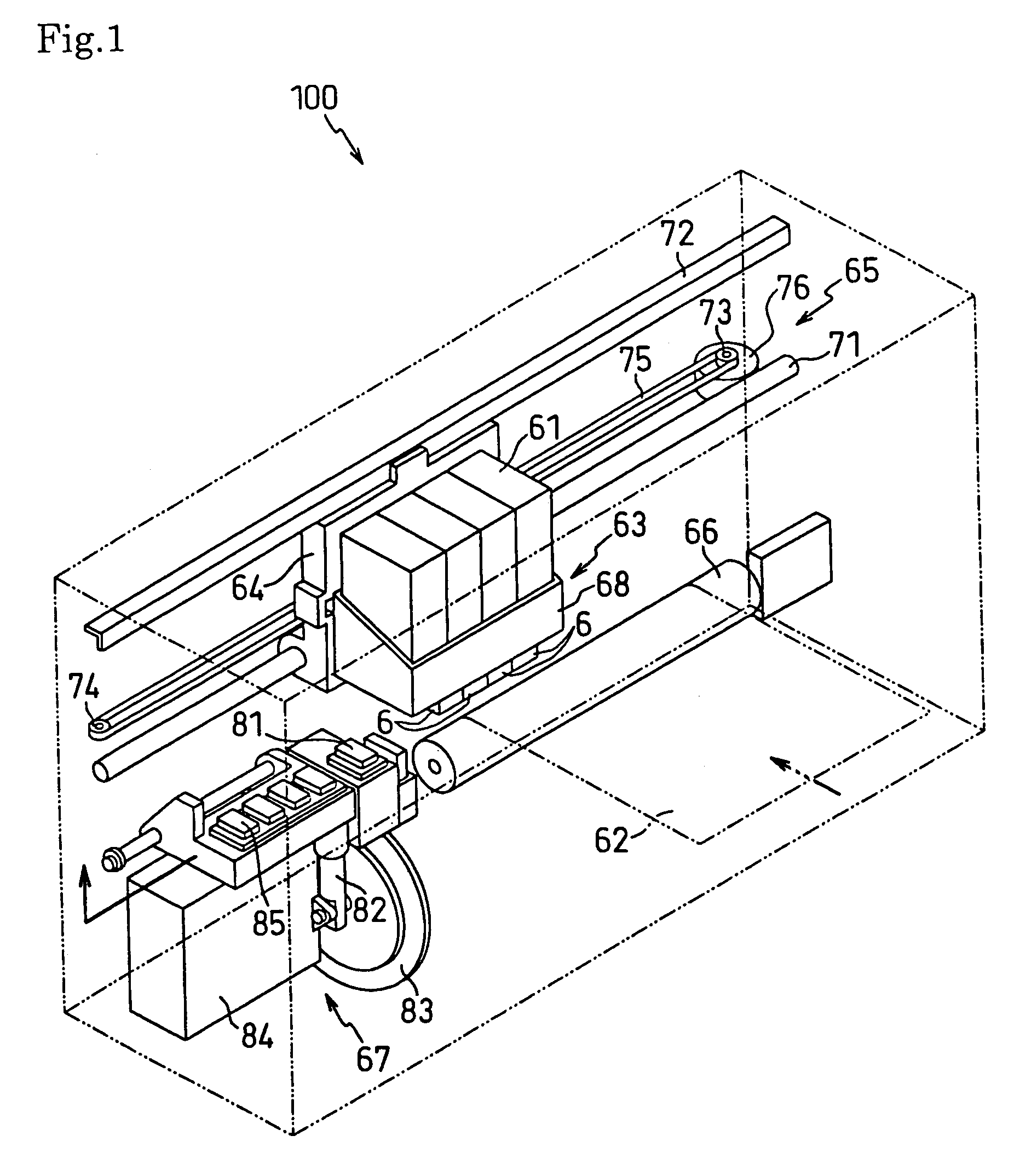
[0054]FIG. 5 is a perspective view of an ink-jet head 6 according to a first embodiment. The ink-jet head 6 includes a rectangular passage unit 10 having a structure in which thin flat plates are laminated. A plate-type piezoelectric actuator (hereinafter referred to as an “actuator”) 20 is bonded and laminated to the passage unit 10 through an adhesive or an adhesive sheet. Further, the flexible flat cable 40 for electrical connection to the circuit substrate 45 is overlapped with and is bonded to the upper surface of the actuator 20 through an adhesive. Many nozzles 35 are opened at the lower surface side (the side opposite to the platen roller 66) of the passage unit 10, and ink is ejected downward from the respective nozzles 35.

[0055]FIG. 6 is an exploded perspective view of the passage unit 10, and FIG. 7 is an exploded enlarged perspective view (section in a VII—VII direction of FIG. 6) of the passage unit 10. As shown in FIGS. 6 and 7, the passage unit...

second embodiment

[0102][Second Embodiment]

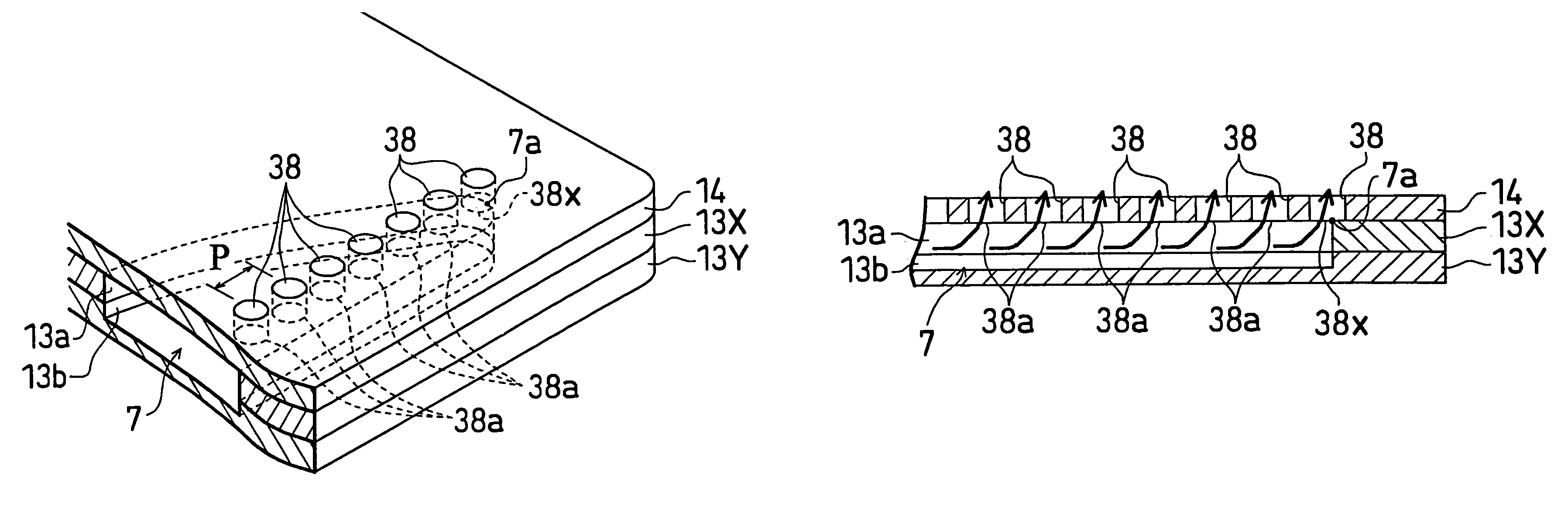
[0103]FIGS. 17 to 19 show an ink-jet head 6′ of a second embodiment. In the ink-jet head 6′, its passage unit 10′ has a structure in which five flat plates in total, that is, a nozzle plate 11, two manifold plates 13X and 13Y′, a spacer plate 14, and a base plate 15′ are laminated. That is, the damper plate 12 in the first embodiment is omitted. Since the structure of the nozzle plate 11, the upper manifold plate 13X, and the spacer plate 14 are quite equal to the first embodiment, their description will be omitted.

[0104]In the lower manifold plate 13Y′, two ink chamber half parts 13b′ and 13b′ are provided to pass through a plate thickness, not to be concave. The four flat plates, that is, the spacer plate 14, the upper manifold plate 13X, the lower manifold plate 13Y′, and the nozzle plate 11 are laminated, so that the ink chamber half part 13b′ is connected to the ink chamber half part 13a of the upper manifold plate 13X, and the common ink chamber 7 is f...


PUM


Abstract

An ink-jet head includes a plurality of nozzles, a plurality of pressure chambers corresponding to the nozzles and connected to the nozzles, a common ink chamber for supplying ink to the pressure chambers, a supply passage for supplying ink to the common ink chamber, a plurality of connection passages corresponding to the respective pressure chambers, one ends of which are connected to the common ink chamber and the other ends of which are connected to the respective pressure chambers, a first member forming the common ink chamber, and a second member connected to the first member and having openings of the connection passages aligned in a surface at a side of the first member. A projection of an opening, positioned at a most downstream end in an ink flowing direction from the supply passage in the common ink chamber, on the first member in a connecting direction straddles a contour of the common ink chamber.

Description

BACKGROUND OF THE INVENTION[0001]1. Field of the Invention[0002]The present invention relates to a structure of an ink-jet head for forming an image by ejecting minute ink droplets onto a printing surface.[0003]2. Description of Related Art[0004]Conventionally, as a recording apparatus which has a simple structure and enables high speed and high quality printing, an ink-jet system recording apparatus is well known.[0005]As a ink-jet head of the ink-jet system recording apparatus, for example, an ink-jet head of a flat plate lamination structure is known which includes a plurality of nozzles for ejecting ink onto a recording medium such as a paper, a plurality of pressure chambers provided correspondingly to the respective nozzles and connected to the nozzles, a common ink chamber for distributing and supplying ink to the pressure chambers through connection passages, and a supply passage for supplying the ink to the common ink chamber.[0006]In this structure, the ink supplied to the...

Claims


Application Information

Patent Timeline
Patent Type & Authority Patents(United States)
IPC IPC(8): B41J2/14
CPCB41J2/14209B41J2002/14217B41J2002/14225B41J2002/14419
Inventor ITO, ATSUSHISAKURAI, HISAKI
Owner BROTHER KOGYO KK
Why Eureka
Try Eureka