[0013]The present invention provides both a method and an apparatus for evaluating and / or indicating binocular performance of spectacle lenses when a visual field is seen by an observer through right and left spectacle lenses. In a first preferred method embodiment in accordance with the present invention, a method for indicating binocular performance of spectacle lenses when a visual field is seen by an observer through right and left spectacle lenses is characterized by the steps of: (1) defining a binocular performance index expressing a binocular performance of the spectacle lenses for viewing an object point in a visual field to obtain a binocular performance index definition; (2) deriving a binocular performance index for each of a plurality of object points distributed over the visual field using the binocular performance index definition: and (3) displaying the scale of the obtained binocular performance indexes in a visually understandable mode.
[0014]In a second preferred method embodiment in accordance with the present invention, a method for indicating binocular performance of spectacle lenses when a visual field is seen by an observer through right and left spectacle lenses characterized by the steps of: (1) defining a binocular performance index expressing a binocular performance of the spectacle lenses for viewing an object point in a visual field to obtain a binocular performance index definition; (2) deriving a binocular performance index for all object points in the visual field using the binocular performance index definition, each object point having a binocular performance index and corresponding to a pixel of an image which covers the visual field; and (3) creating a binocular performance index image covering the visual field, wherein a monochromatic or RGB color luminosity of each pixel is assigned to indicate a value of the binocular performance index for viewing the corresponding object point.
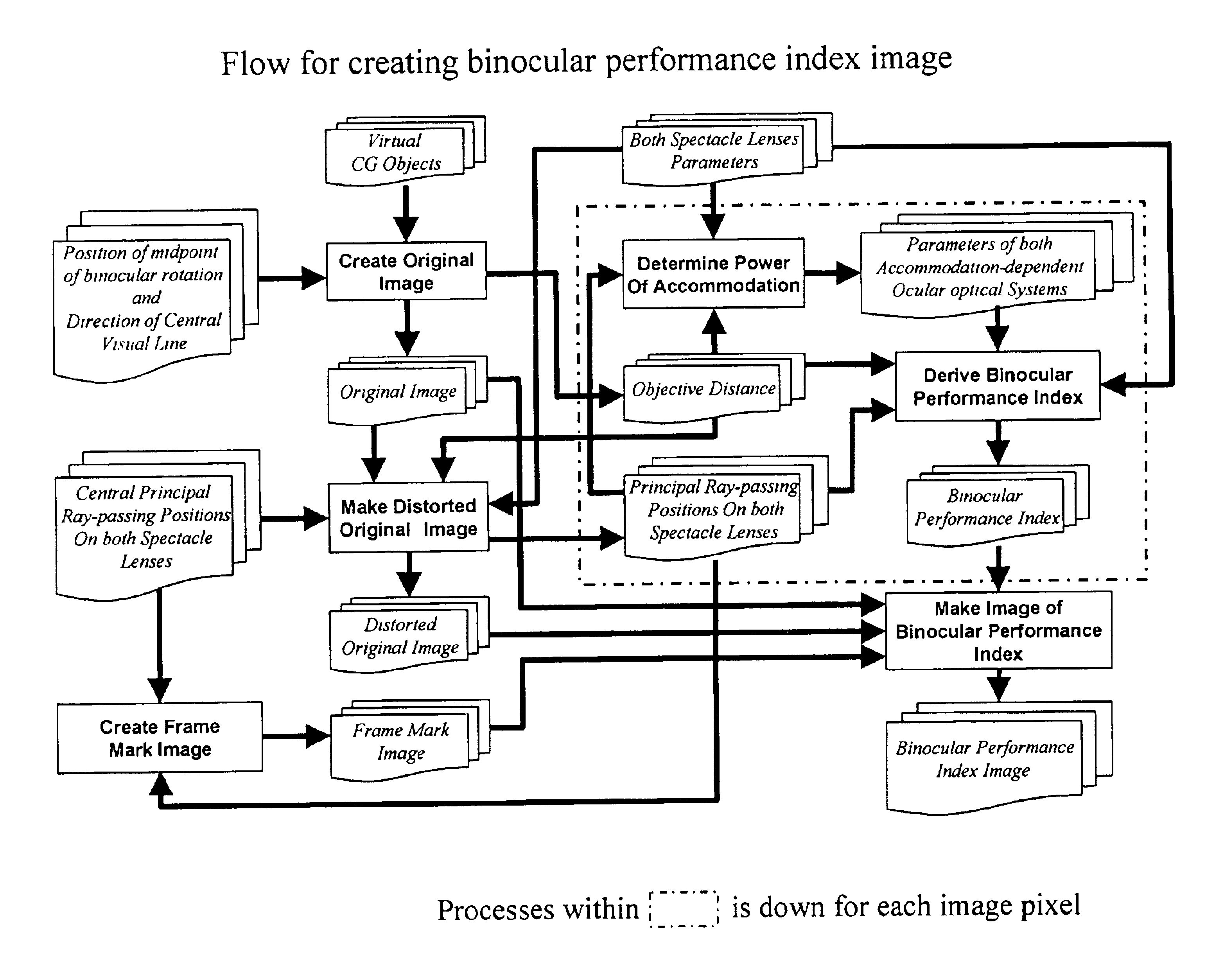
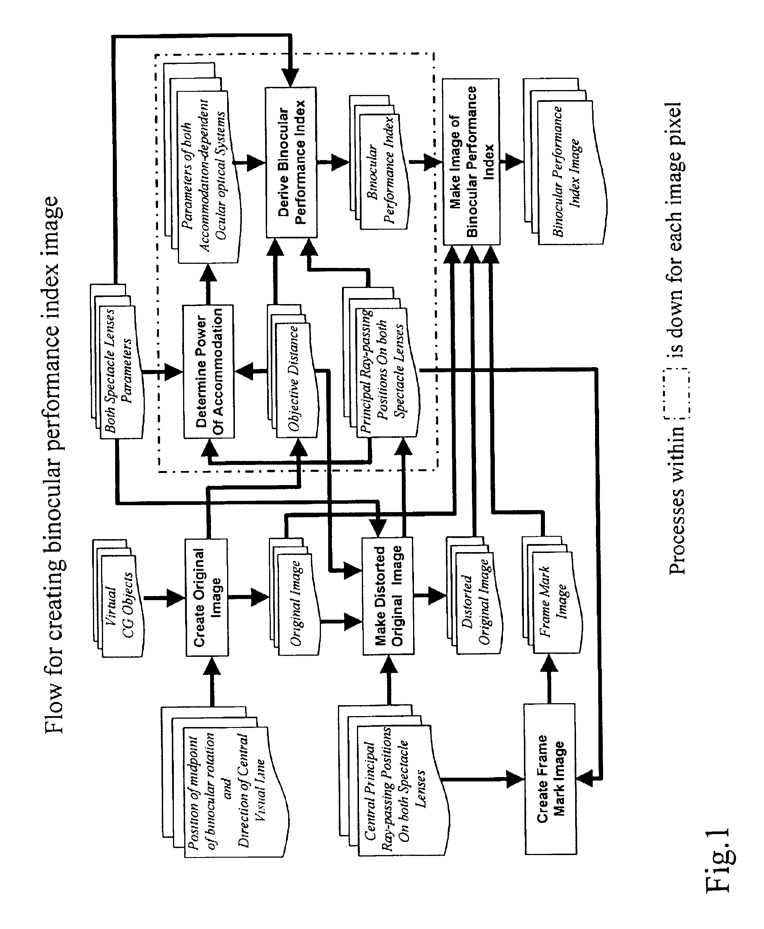
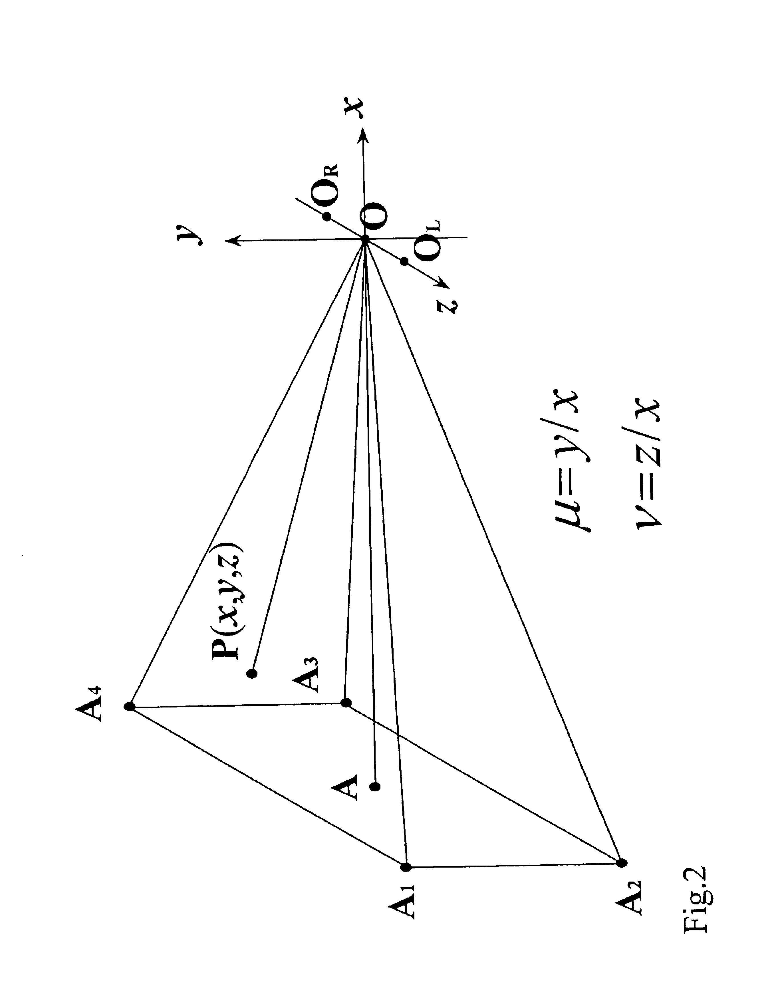
[0015]In accordance with a first preferred apparatus embodiment of the present invention, an apparatus for indicating binocular performance of spectacle lenses when an observer sees through right and left spectacle lenses, is characterized by: (a) means for creating an original image, further comprising: (i) means for creating virtual objects by using computer graphics and placing the virtual objects in a virtual three-dimensional space; (ii) means for placing a midpoint of binocular rotation at a specific position in the virtual three-dimensional space; (iii) means for creating an original image of the virtual objects within a visual field, the visual field defined as a pyramid having an apex located at the midpoint of binocular rotation and a central axis oriented along a direction of a specific central visual line; and (iv) means for deriving, with respect to a plurality of object points, each object point corresponding to a pixel of the original image, an object distance, wherein the object distance is defined as a distance between the object point and the midpoint of binocular rotation; (b) means for creating a distorted original image, further comprising: (i) means for defining a direction of synkinetic binocular rotation for viewing an object point, wherein the synkinetic binocular rotation is uniquely determined by both directions of monocular rotation for right and left eyeballs directed toward the object point; (ii) means for deriving a central direction of synkinetic binocular rotation with a ray tracing method so that each of right and left monocular central principal rays pass through a specific position on each spectacle lens, respectively, wherein the central direction of synkinetic binocular rotation is the direction of synkinetic binocular rotation for viewing the object point located at a center of the visual field and the right and left monocular central principal rays are principal rays directed from the right and left eyeballs, respectively, toward the central object point; (iii) means for deriving, with respect to each object point, a direction of synkinetic binocular rotation for viewing the object point as a position of the object point in an after-lens visual field with a ray tracing method, wherein the after-lens visual field is a visual field that has a central axis oriented along the central direction of synkinetic binocular rotation; (iv) means for creating a distorted original image, the distorted original image being defined as an image obtained in the after-lens visual field and having distortion caused by the spectacle lenses; and (v) means for deriving, with respect to each object point, both right and left principal ray-passing positions, wherein each principal ray-passing position is a position on the respective spectacle lens through which a principal ray directed toward the object point passes; (c) means for deriving positions of spectacle frames by creating images of spectacle frame marks that indicate positions of right and left spectacle frames on the original image, or on the distorted original image, by using data of the principal ray-passing positions determined when creating a distorted original image; (d) means for deriving a binocular performance index, further comprising: (i) means for providing an accommodation-dependent ocular optical system for each of the right and left eyes as a model of the ocular optical system; (ii) means for calculating, with respect to each object point corresponding to a pixel of the original image or the distorted original image, distances from the object point to the right and left centers of monocular rotation using the object distance obtained when creating an original image; (iii) means for setting, with respect to each object point corresponding to a pixel of the original image or the distorted original image, powers of accommodation of right and left eyes to a same value or to different values in accordance with each distance from the object point to each center of monocular rotation, and each refractive power of spectacle lens at each principal ray-passing position determined when creating a distorted original image; and (iv) means for deriving, with respect to each object point corresponding to a pixel of the original image or the distorted original image, a binocular performance index of spectacle lenses in a combined optical system comprising the spectacle lens and the accommodation-dependent ocular optical system which is rotated in accordance with a direction of monocular rotation; and (e) means for creating a binocular performance index image, further comprising: (i) means for creating the binocular performance index image by assigning, to each pixel of the original image or the distorted original image, a monocular luminance or luminances of three primary colors of RGB determined in accordance with a value of the binocular performance index of spectacle lenses, and (ii) means for overlaying the binocular performance index image with the frame mark images of spectacle frames created when deriving positions of spectacle frames.
[0016]The advantages of the present invention are summarized as follows. As described above in detail herein, a binocular performance index of spectacle lenses, which expresses the binocular performance of spectacle lenses when each object point in the visual field is seen by an observer, is defined and derived. The binocular performance of the spectacle lenses is evaluated using the derived binocular performance index and the result of the evaluation is displayed. Due to the evaluation and the display, the binocular performance of spectacle lenses can be evaluated and displayed in a condition very close to the actual use of the spectacle lenses.

