Epoxy bonded fiber optic connector and method of constructing same

a fiber optic connector and epoxy bonding technology, applied in the field of epoxy bonding fiber optic connectors and the method of constructing them, can solve the problems of limiting the amount of tension the connection can bear, inventory and delivery problems, and bulky cables with a limited number of break-out tubes

Inactive Publication Date: 2005-12-27
JOHN MEZZALINGUA ASSOC INC
View PDF2 Cites 26 Cited by
  • Summary
  • Abstract
  • Description
  • Claims
  • Application Information

AI Technical Summary

Problems solved by technology

Because of the wide range of available trunk cables specified by customers, a large number of different clamps must be stocked to fit all cable sizes, leading to inventory and delivery problems.
In addition, such clamps grip only the polyethylene outer jacket of the cable rather than gripping the strength members directly, thus limiting the amount of tension the connection can bear.
Furthermore, the heat shrink process is labor intensive, resulting in bulky cables with a limited number of break-out tubes that fit inside the connector.

Method used


Image

  • Epoxy bonded fiber optic connector and method of constructing same
  • Epoxy bonded fiber optic connector and method of constructing same
  • Epoxy bonded fiber optic connector and method of constructing same

Examples


Embodiment Construction

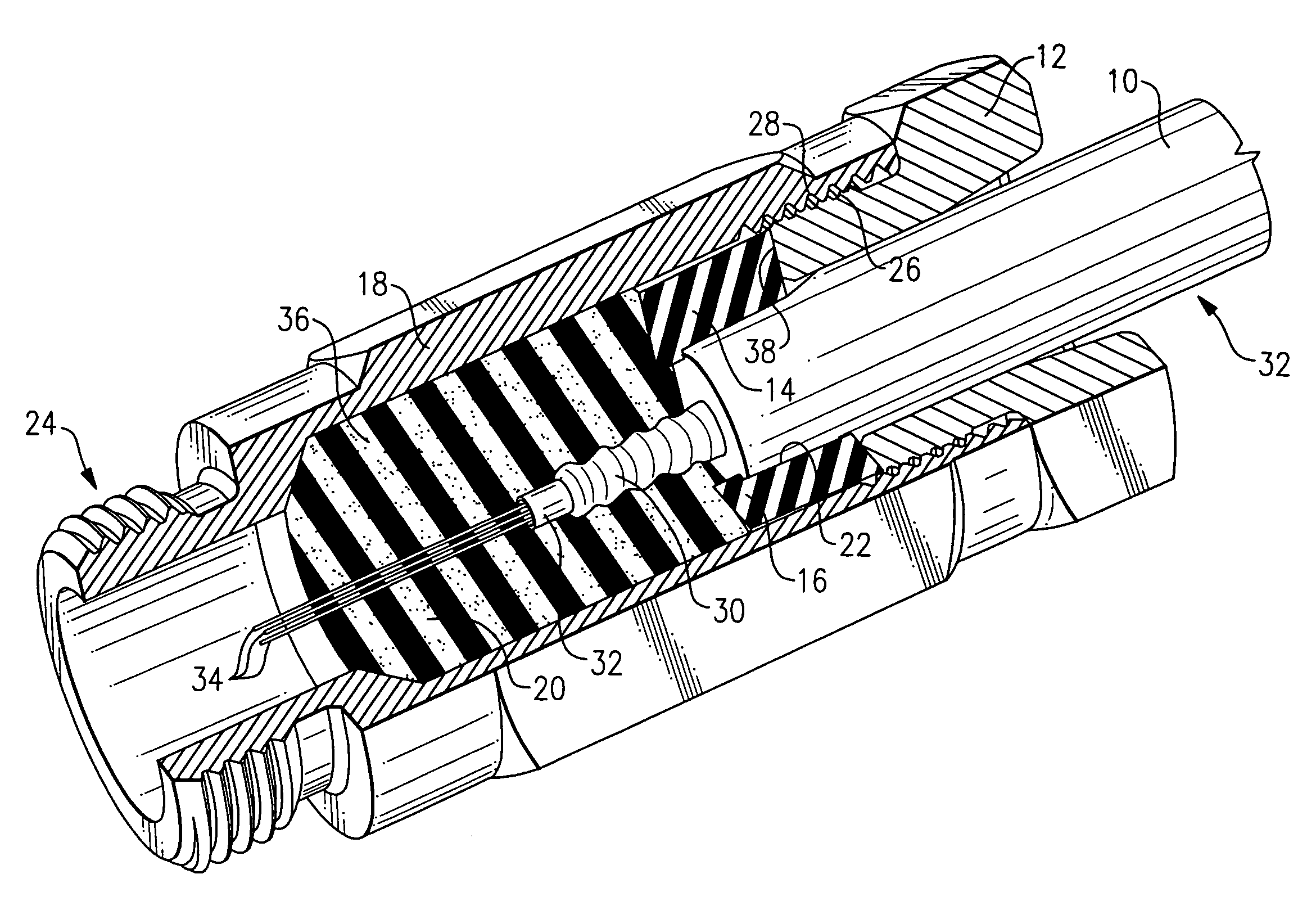
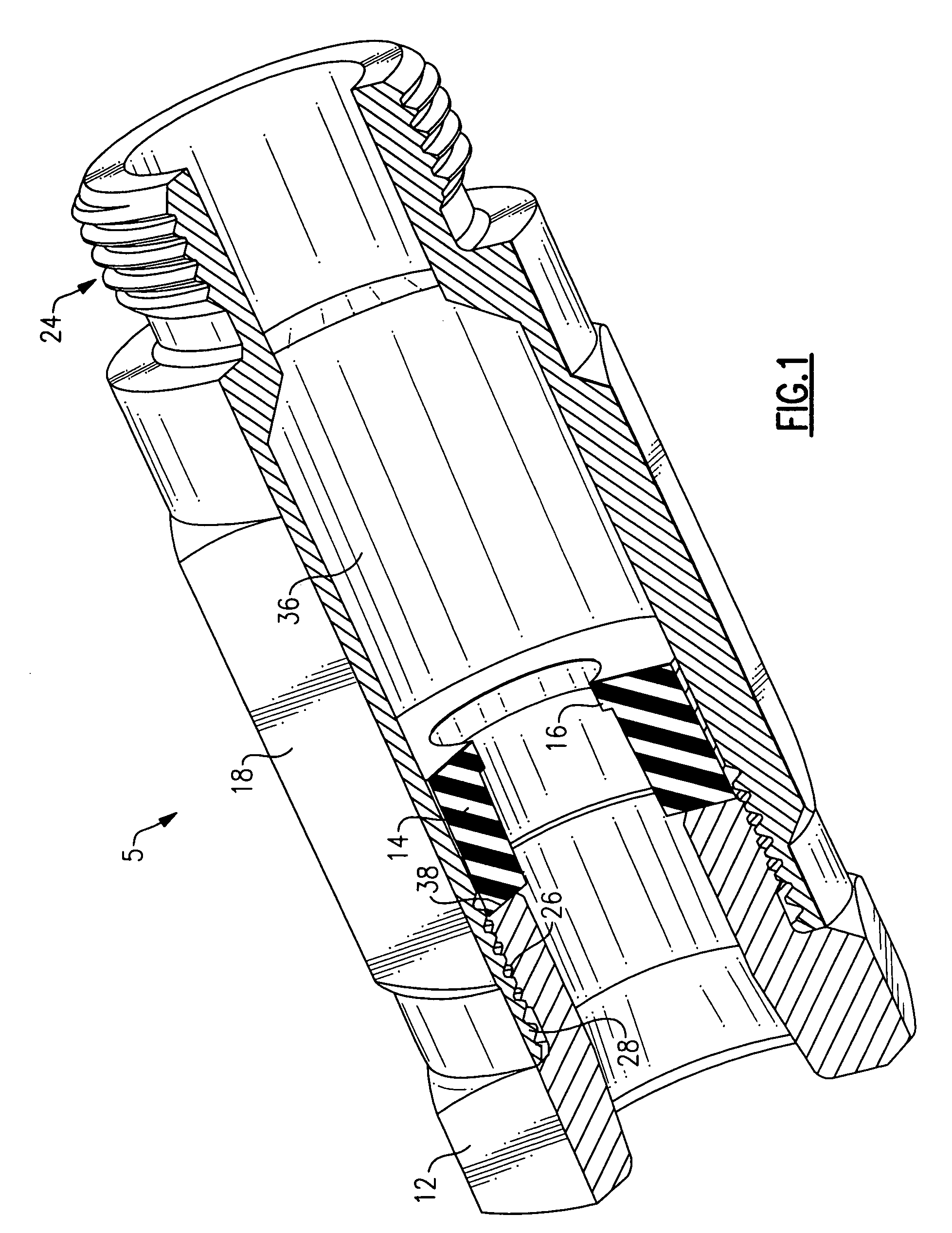
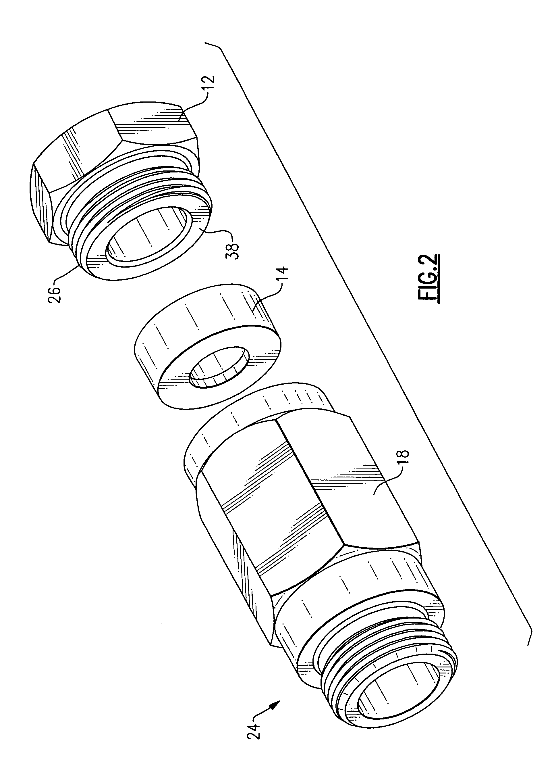
[0012]Referring to FIGS. 1–3, a connector 5 includes a body 18 with a threaded connection end 24 which screws into an equipment port or the like. The other end of body 18 includes a plurality of internal threads 28 which engage with a plurality of external threads 26 of a nut 12. A driving surface 38 of nut 12 pushes against a seal 14, forcing seal 14 into body 18. Seal 14 is preferably an elastomeric seal with limited resilience. When the external threads 26 of nut 12 are fully engaged with the internal threads 28 of body 18, seal 14 marks one end of a cavity 36 inside body 18. The other end of cavity 36 is bounded by threaded connection end 24. Seal 14 includes a shoulder 16, the purpose of which is explained below.

[0013]Referring to FIG. 4, a conventional fiberoptic cable 32 is prepared so that a cable sheath 10 is stripped away, leaving an inner armor or sheathing 30 with a plurality of breakout tubes 34 extending from sheathing 30. Cable 32 is inserted through the back of nut 1...


PUM


Abstract

A connector for releasable engagement of a fiberoptic cable with a port on a piece of compatible equipment includes a body of generally cylindrical form which includes a cavity. After a prepared cable end of the fiberoptic cable is inserted through a driving structure and registered against a seal, and the combination placed in a pre-form mold, an epoxy material is flowed into the mold to surround portions of the prepared cable end, thereby creating an assembly consisting of the prepared cable end, the seal, and the hardened epoxy material. The assembly is then disposed inside the cavity of the body after which the assembly is secured to the body using a nut or compression fitting.

Description

FIELD OF THE INVENTION[0001]This invention relates generally to the field of connectors for coupling fiber optic cables to an equipment port, and more particularly to a fiber optic connector with epoxy bonding and sealing the connector to the fiber optic cable.BACKGROUND OF THE INVENTION[0002]Connectors used to secure the strength members and jacket of a fiber optic cable to an equipment port with a load-bearing, weather-tight connection while allowing the signal-carrying fibers of the cable to pass into the equipment housing are known. One type of prior art design of such connectors uses specially sized mechanical clamps to secure the cable to the connector and heat-shrink tubing to secure the break-out tubing to the cable. Because of the wide range of available trunk cables specified by customers, a large number of different clamps must be stocked to fit all cable sizes, leading to inventory and delivery problems. In addition, such clamps grip only the polyethylene outer jacket of...

Claims


Application Information

Patent Timeline
Patent Type & Authority Patents(United States)
IPC IPC(8): G02B6/36G02B6/38G02B6/44
CPCG02B6/3887G02B6/4477G02B6/3889
Inventor MONTENA, NOAH
Owner JOHN MEZZALINGUA ASSOC INC
Why Eureka
Try Eureka