
Push-in removable fastener

Inactive Publication Date: 2005-12-27
ILLINOIS TOOL WORKS INC
View PDF39 Cites 45 Cited by
  • Summary
  • Abstract
  • Description
  • Claims
  • Application Information

AI Technical Summary

Benefits of technology

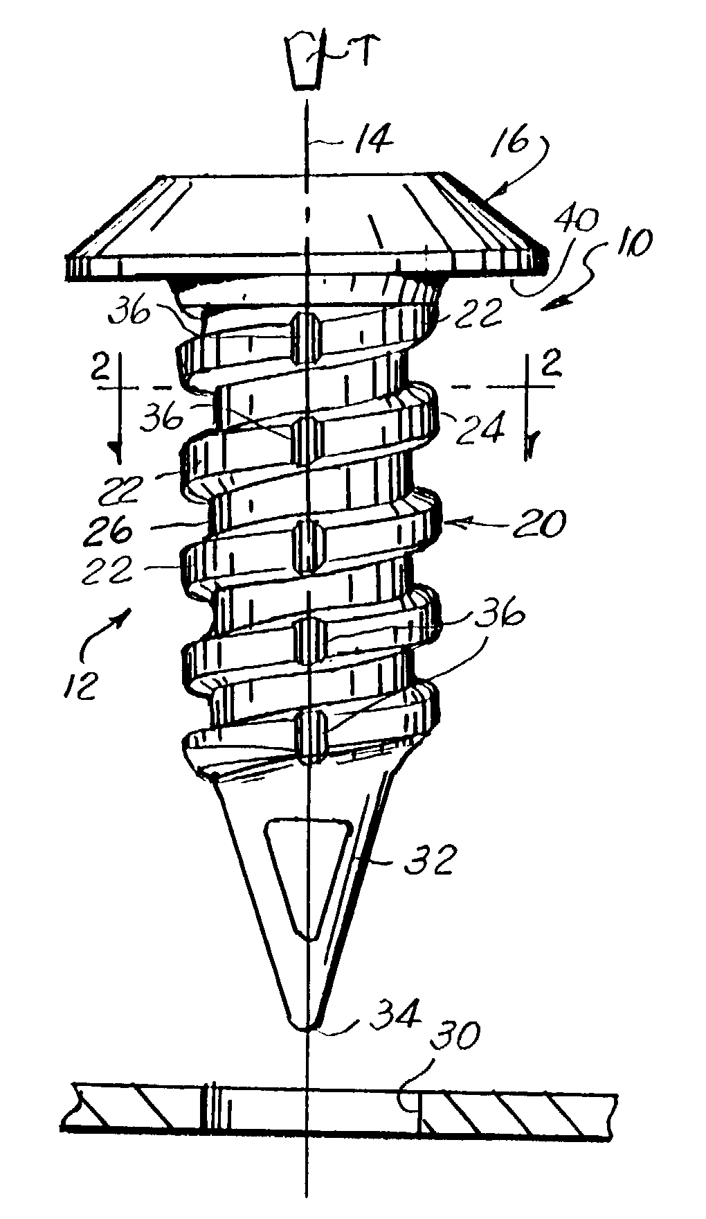
[0009]In view of the above, and in accordance with the present invention, there is provided a push-in type fastener which solves the heretofore known problems associated with these type fasteners. The fastener of the present invention has an enlarged head and a shank. The fastener is configured to allow the shank to be pushed through a complementary shaped aperture or opening in an article using a relatively low insertion force. A series of convolutions form a helical screw or rib formation on the fastener shank which opposes the fastener from being axially withdrawn from the article while readily permitting withdrawal of the fastener from the article in response to rotation of the fastener about its axis. Moreover, the fastener shank is configured to prevent inadvertent removal or separation of the fastener from the article through which it passes.
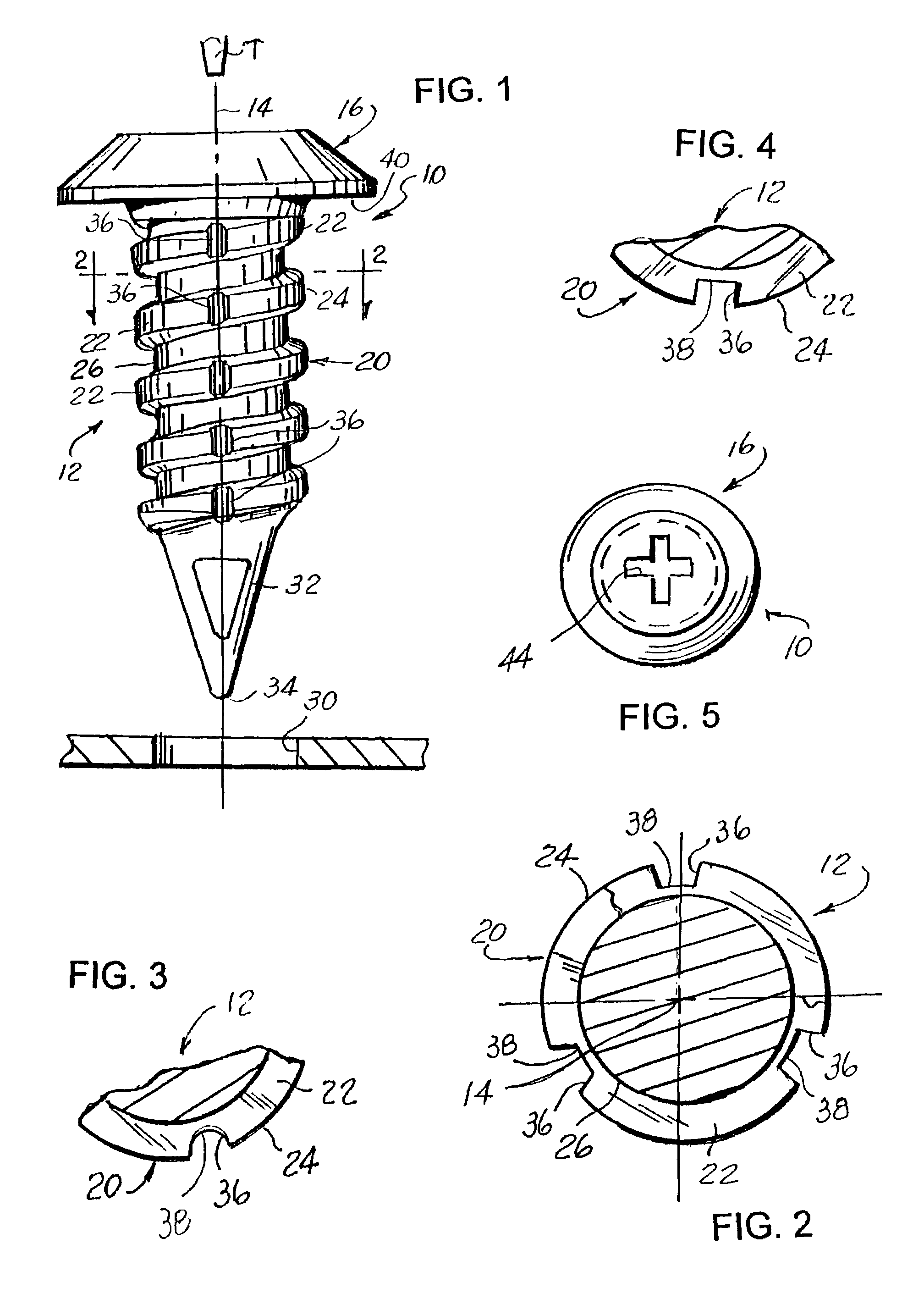
[0010]Preferably, the convolutions are configured such that the helical screw or rib formation on the fastener shank has an incomplete formation extending about the peripheral edge thereof. In one form, one or more convolutions comprising the helical screw or rib formation on the fastener shank are each configured with at least one recess or serration which opens to a crest diameter of the screw formation. An innermost edge of each recess or serration, however, preferably terminates radially outwardly from a root diameter of the respective screw or rib convolution. Besides resisting inadvertent rotation of the fastener about its axis, a threaded fastener shank so configured advantageously reduces fastener installation force by approximately twenty-five percent as comparted to fully threaded fasteners.
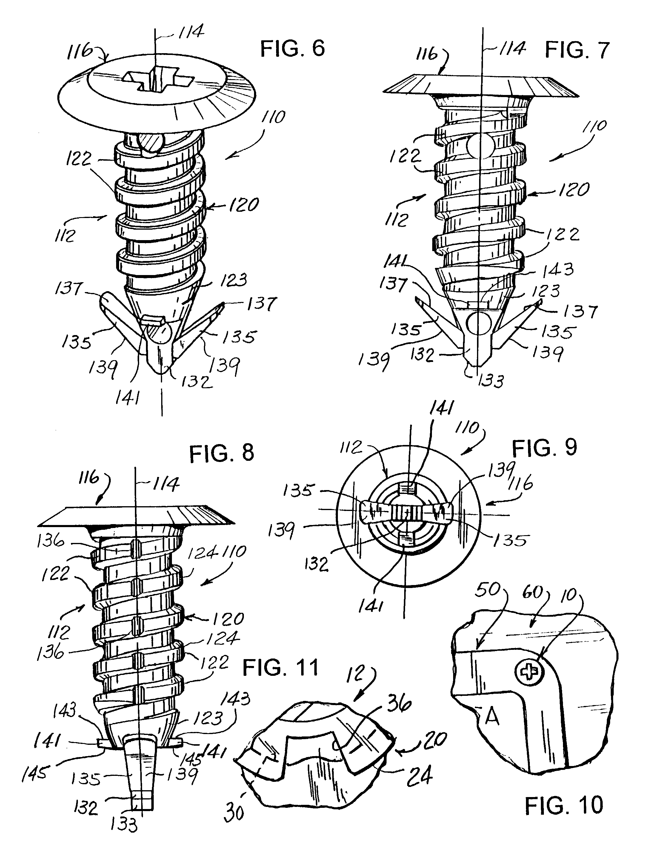
[0011]In another form of fastener, and besides configuring the fastener shank with a helical screw or rib formation, a pair of resilient wings or elements are joined and extend outwardly from opposed sides of the fastener shank free end. Each wing or element extends outwardly relative to the fastener axis a further radial distance than does the helical screw or rib formation on the fastener shank and, preferably, is inclined or slants toward the fastener head. Each wing or element is flexible in a direction toward the fastener head but is resistant to deflection in a direction away from the fastener shank whereby resisting inadvertent removal of the fastener from the opening in the article through which it passes. In a most preferred embodiment, guide structure is provided toward the free end of the threaded shank to facilitate self-centering of the threaded shank and the opening through which it is adapted to pass

Problems solved by technology

A problem arises, however, when the nameplate or article held by the fastener is to be removed from the container.
Since conventional tree fasteners are typically designed to exert high retention force following their insertion, extensive efforts are often required when the nameplate or article held by the fastener is to be removed.
As will be appreciated, such extensive efforts at replacing the nameplate or the like is not conducive to repetitive use of such containers along with required timely turn around of the product stored and transported therewithin
Accordingly, the nameplate or article held by the fastener is typically torn or pulled from the container often resulting in destruction of the nameplate, container, or both, as well as destruction of the fastener.
Of course, requiring a new or replacement nameplate adds to the transportation costs of the product.
Moreover, when the nameplate or article is torn from the container, such action frequently results with the fastener head being broken off from the shank.
As will be appreciated, this requires a labor intensive effort resulting in the waste of valuable time in a highly competitive market.
Moreover, forcible removal of the broken fastener frequently results in the hole through which the fastener is inserted to become enlarged, thus, adversely effecting the holding ability of the replacement fastener used to secure a replacement nameplate to the container.

Method used


Image

  • Push-in removable fastener
  • Push-in removable fastener
  • Push-in removable fastener

Examples


Embodiment Construction

[0029]While the present invention is susceptible of embodiment in multiple forms, there is shown in the drawings and will hereinafter be described preferred embodiments of the invention, with the understanding the disclosure is to be considered as setting forth exemplifications of the invention which are not intended to limit the invention to the specific embodiments illustrated and described.

[0030]Referring now to the drawings, wherein like reference numerals indicate like parts throughout the several views, in FIG. 1 there is shown one form of fastener, which embodies principals of the present invention, and is generally identified by reference numeral 10. Fastener 10 is preferably formed in one piece and comprises an axially elongated shank 12 defining an axis 14 for the fastener 10 and which depends from one side of an enlarged head 16. Fastener 10 can be injection molded from any of the polymeric resins, or plastic materials commonly used for the manufacture of these fasteners ...


PUM


Abstract

A plastic push-in or drive fastener having a enlarged head and a shank is disclosed. The fastener is configured to allow the shank to be pushed through a complementary shaped aperture or opening in an article using a relatively low insertion force. A helical screw or rib formation on the fastener shank provides a retention force opposing the fastener from being axially withdrawn from the article while readily permitting withdrawal of the fastener from the article in response to rotation of the fastener about its axis. Moreover, the fastener shank is configured to prevent inadvertent separation of the fastener from the article through which it passes.

Description

CROSS REFERENCE TO RELATED APPLICATION[0001]This application claims benefit of provisional patent application Ser. No. 60 / 327,491, filed Oct. 5, 2001.FIELD OF THE INVENTION[0002]The present invention generally relates to the fastener art, and more particularly, to a fastener of the type generally referred to as a “push-in” or “drive” fastener but which is rotatably removable so as to permit the fastener to be reused.BACKGROUND OF THE INVENTION[0003]“Push-in” or “drive” fasteners of a variety of types and styles are well known in the fastener art. Typically, such fasteners have a shank with series of vertically spaced flexible tabs or wing-like members extending away from an axis of the fastener. As such, fasteners of this variety are also referred to as tree fasteners.[0004]Such fasteners are driven axially into preformed openings or holes in a workpiece article with the flexible tabs or wings-like members engaging the article and flexing as they move through opening or hole in the ...

Claims


Application Information

Patent Timeline
IPC IPC(8): F16B5/06F16B21/08
CPCF16B21/084F16B21/086F16B2005/0671
Inventor BRLETICH, MICHAEL F.JANISCH, JR., JOSEPH
Owner ILLINOIS TOOL WORKS INC
Learn More