Multiple subscriber videoconferencing system

Active Publication Date: 2005-12-27
MARGALLA COMM
View PDF15 Cites 182 Cited by
  • Summary
  • Abstract
  • Description
  • Claims
  • Application Information

AI Technical Summary

Benefits of technology

[0012]According to another embodiment of the invention, the method may include installing a video services switch on a service provider network at an access point configured to enable multiple enterprise subscribers to access a global packet-switched computer network to exchange data, including videoconferencing data and non-videoconferencing data. The video services switch is typically configured to process videoconferencing data from multiple enter

Problems solved by technology

However, ISDN videoconferencing is extremely expensive, because ISDN lines are costly to install and lease, and because specialized hardware is required at the sites of the users.
In addition, ISDN can be complicated to set up, and unreliable.
Videoconferencing over IP networks has a number of fundamental problems, including security, bandwidth utilization, quality of service, and deployment and management.
Regarding security, H.323 and SIP are difficult to implement with current firewalls.
The difficulty lies in the fact that H.323 and SIP are complex protocols and use multiple dynamically allocated ports for each call.
Because of the heavy use of dynamically allocated ports, it is not possible to preconfigure firewalls to allow SIP- or H.323-signaled traffic without opening up large numbers of holes in the firewall.
In addition, SIP or H.323 video endpoints behind a firewall typically cannot receive calls from external parties due to firewall policies in place at most enterprises.
The problem with sending H.323 and SIP traffic through a NAT device is that these protocols make heavy use of embedded IP addresses, while normal data traffic contain IP address in the header of each packet.
While configuring a NAT to rewrite packet headers to change addresses is relatively straightforward, it is very difficult to configure a NAT to translate addresses that are embedded in H.323 and SIP traffic, because the location of these address in these data stream is difficult to calculate.
Current systems do not allow a network administrator to control easily the bandwidth usage of multiple network users.
Therefore, network administrators are reluctant to deploy videoconferencing systems.
Regarding quality of service, t

Method used


Image

  • Multiple subscriber videoconferencing system
  • Multiple subscriber videoconferencing system
  • Multiple subscriber videoconferencing system

Examples


Embodiment Construction

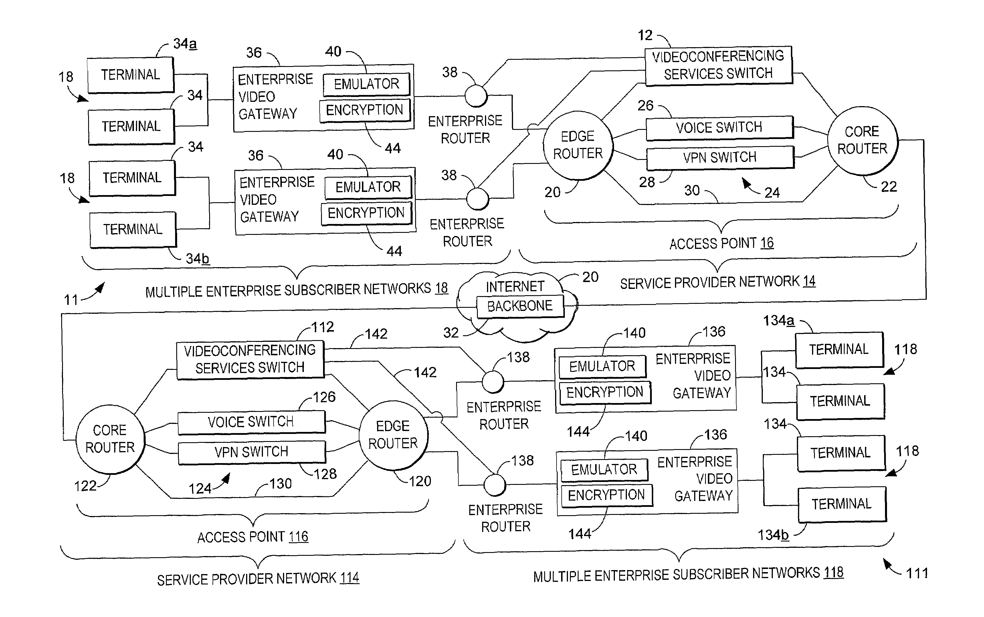
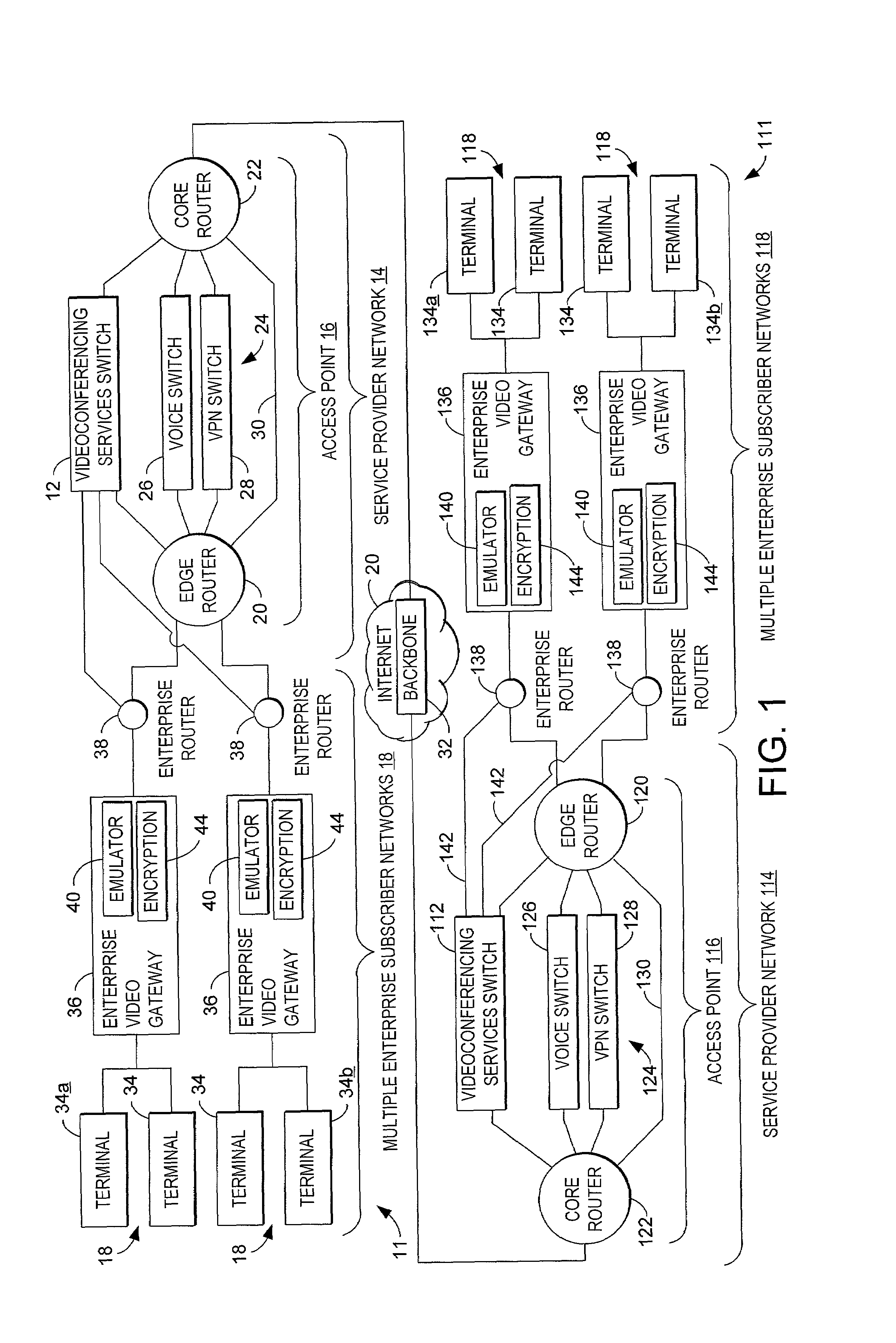
[0026]Referring initially to FIG. 1, a videoconferencing system according to one embodiment of the present invention is shown generally at 10. System 10 typically includes a videoconferencing services switch (VSS) 12 positioned on a service provider network 14 at an access point 16, typically a point of presence (POP). Switch 12 is configured to register multiple enterprise subscriber networks 18 for videoconferencing services, receive subscriber-specific settings for each subscriber 18 related to security and management of the videoconferencing calls from that subscriber, and process videoconferencing calls from each subscriber based on the associated subscriber-specific settings.

[0027]Service provider network 14 typically includes a packet-switched Internet Protocol (IP) network through which multiple enterprise subscriber networks 18 may access a global IP network 20, such as the Internet 20. Typically, the service provider network 14 includes an access point 16, such as a POP 16...


PUM


Abstract

A system, method, and device for use in videoconferencing. The method typically includes installing a videoconferencing services switch at an access point to an IP network, and registering a plurality of subscribers for videoconferencing services. Each subscriber typically has a plurality of endpoints. The method further includes receiving subscriber-specific settings to be applied to multiple videoconferencing calls from the plurality of endpoints associated with each subscriber. The method further includes storing the subscriber-specific settings at a location accessible to the switch, and configuring the switch to connect calls from the plurality of endpoints at each subscriber based on the corresponding subscriber-specific settings.

Description

CROSS REFERENCE TO RELATED APPLICATIONS[0001]This application claims priority under 35 U.S.C. § 119(e) to U.S. Provisional Patent Application No. 60 / 191,819 entitled “System and Method for Security and Management of Streaming Data Communications on a Computer Network System,” filed Mar. 24, 2000, the disclosure of which is herein incorporated by reference.TECHNICAL FIELD[0002]The present invention relates generally to videoconferencing, and more particularly to a system, method, and device for implementing a multiple subscriber videoconferencing service for use on Internet Protocol (IP) networks.BACKGROUND OF THE INVENTION[0003]Videoconferencing provides a convenient way for users in distant locations to participate in a face-to-face meeting, without having to spend time and money traveling to a central meeting site. Many prior videoconferencing systems have been based on circuit switched Integrated Services Digital Networks (ISDN) standards. ISDN lines typically offer guaranteed qu...

Claims


Application Information

Patent Timeline
IPC IPC(8): H04L12/18H04L29/06H04L29/12H04Q11/04
CPCH04L12/1813H04L29/06H04L29/12009H04L29/12047H04L29/1233H04L61/15H04L61/25H04L63/0272H04L63/0428H04Q11/04H04L65/4038H04N7/15H04L29/06027H04L63/0281H04L63/164H04Q2213/13034H04Q2213/13103H04Q2213/13106H04Q2213/13109H04Q2213/13166H04Q2213/13196H04Q2213/13204H04Q2213/1329H04Q2213/13335H04Q2213/13337H04Q2213/13339H04Q2213/13348H04Q2213/13389H04Q2213/13399H04L61/45H04L61/00H04L65/1094H04L9/40H04L65/1104H04L65/1101H04L61/2503H04L65/403H04L61/256H04W8/183
Inventor JANG, SAQIBKENT, MARK
Owner MARGALLA COMM
Why Eureka
Try Eureka