Connector for accessories
- Summary
- Abstract
- Description
- Claims
- Application Information
AI Technical Summary
Benefits of technology
Problems solved by technology
Method used
Image

Examples
Embodiment Construction
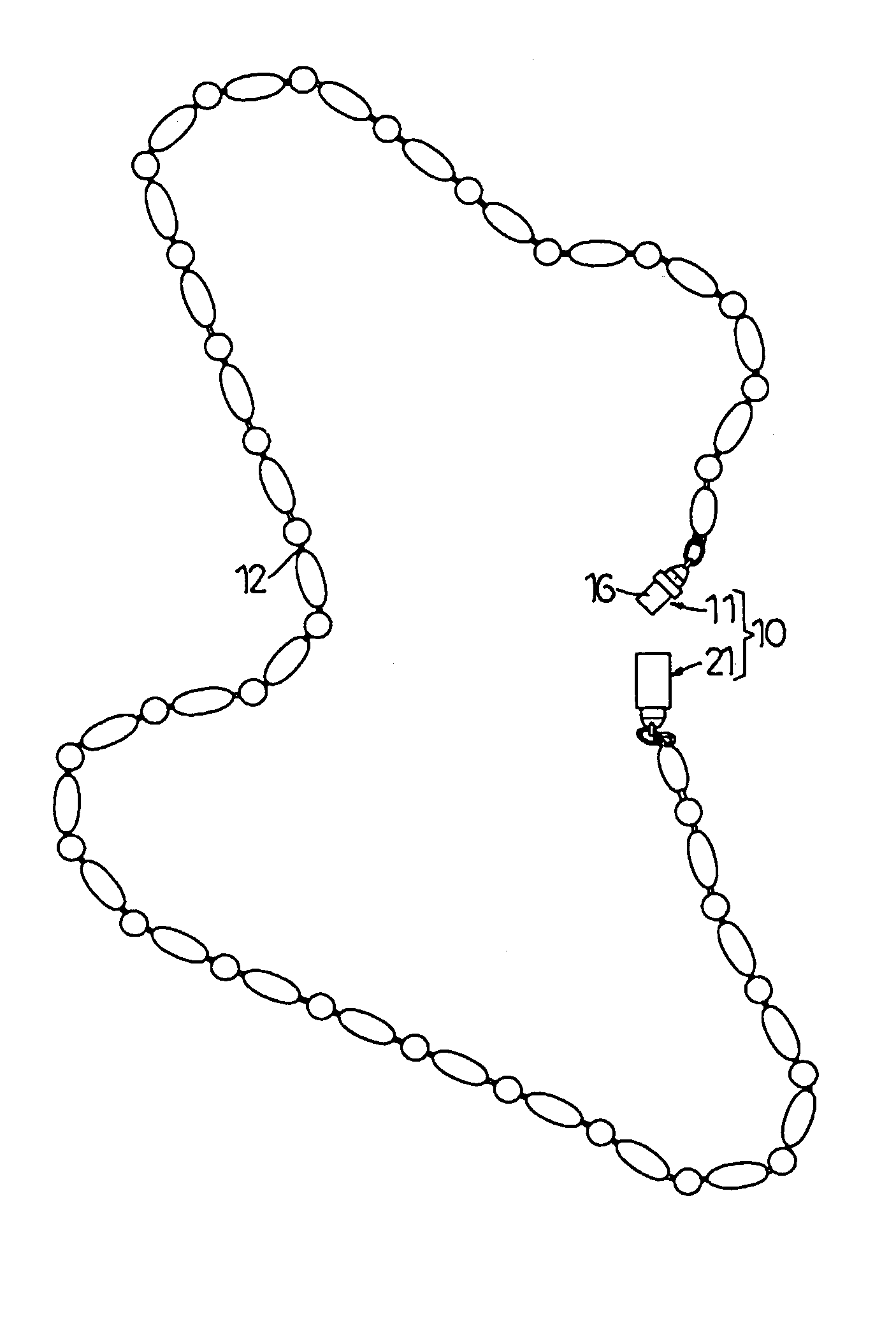
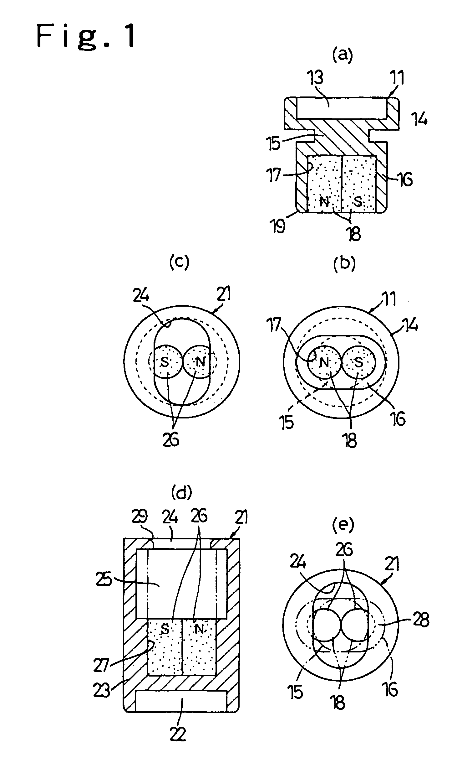
[0031]The invention will be described below in further detail on the basis of embodiments shown in the drawings. FIGS. 1A to 1E show a male part 11 and a female part 21 combined therewith in a connector 10 for accessories, etc., according to the invention.
[0032]The male part 11 as shown in FIGS. 1A and 1B comprises a base 14 provided at one end thereof with a connection 13 for a linear member 12 shown in FIG. 5, a neck 15 provided on a surface opposed to the connection 13, and a head 16 provided outside the neck. The base 14 as illustrated is circular, the neck 15 is circular and smaller than the base 14, and the head 16 is elliptical to have a major axis, which is smaller than a diameter of the base and larger than a diameter of the neck, and a minor axis set to be the same as the diameter of the neck.
[0033]The head 16 is provided on an outer end surface thereof with a recess 17, into which magnets 18 are incorporated. Two magnets 18 are aligned in a longitudinal direction of the e...
PUM
 Abstract
Description
Claims
Application Information
PatSnap Eureka turns technology decisions into work you can execute. Powered by our Innovation Knowledge Graph, it runs expert workflows across engineering, life sciences, materials and intellectual property. Get your review-ready output in minutes.


