Pressure gage and switch

a switch and pressure sensor technology, applied in the field of pressure switches, can solve the problems of affecting the mechanical reading of the pressure being sensed by the switch, affecting the operation of the switch, and requiring a relatively complex and costly mechanical arrangemen

a switch and pressure sensor technology, applied in the field of pressure switches, can solve the problems of affecting the mechanical reading of the pressure being sensed by the switch, affecting the operation of the switch, and requiring a relatively complex and costly mechanical arrangemen

US6981421B2Active Publication Date: 2006-01-03DWYER INSTR

Image

  • Pressure gage and switch
  • Pressure gage and switch
  • Pressure gage and switch

Examples


Embodiment Construction

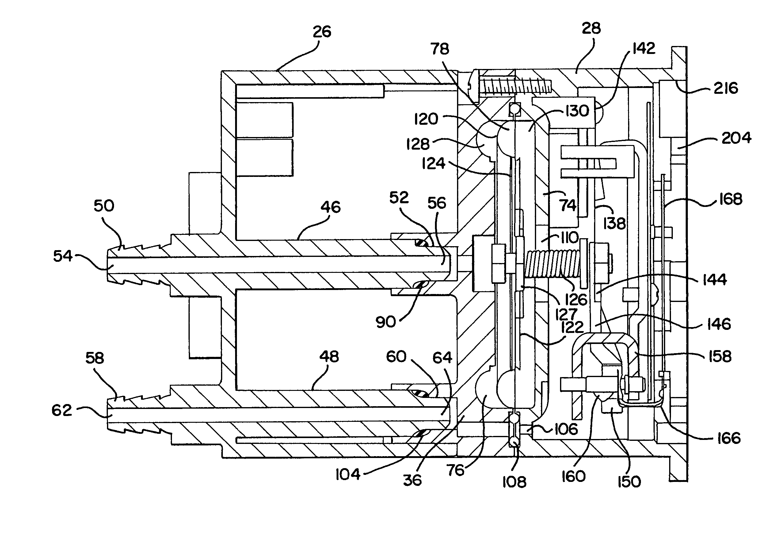
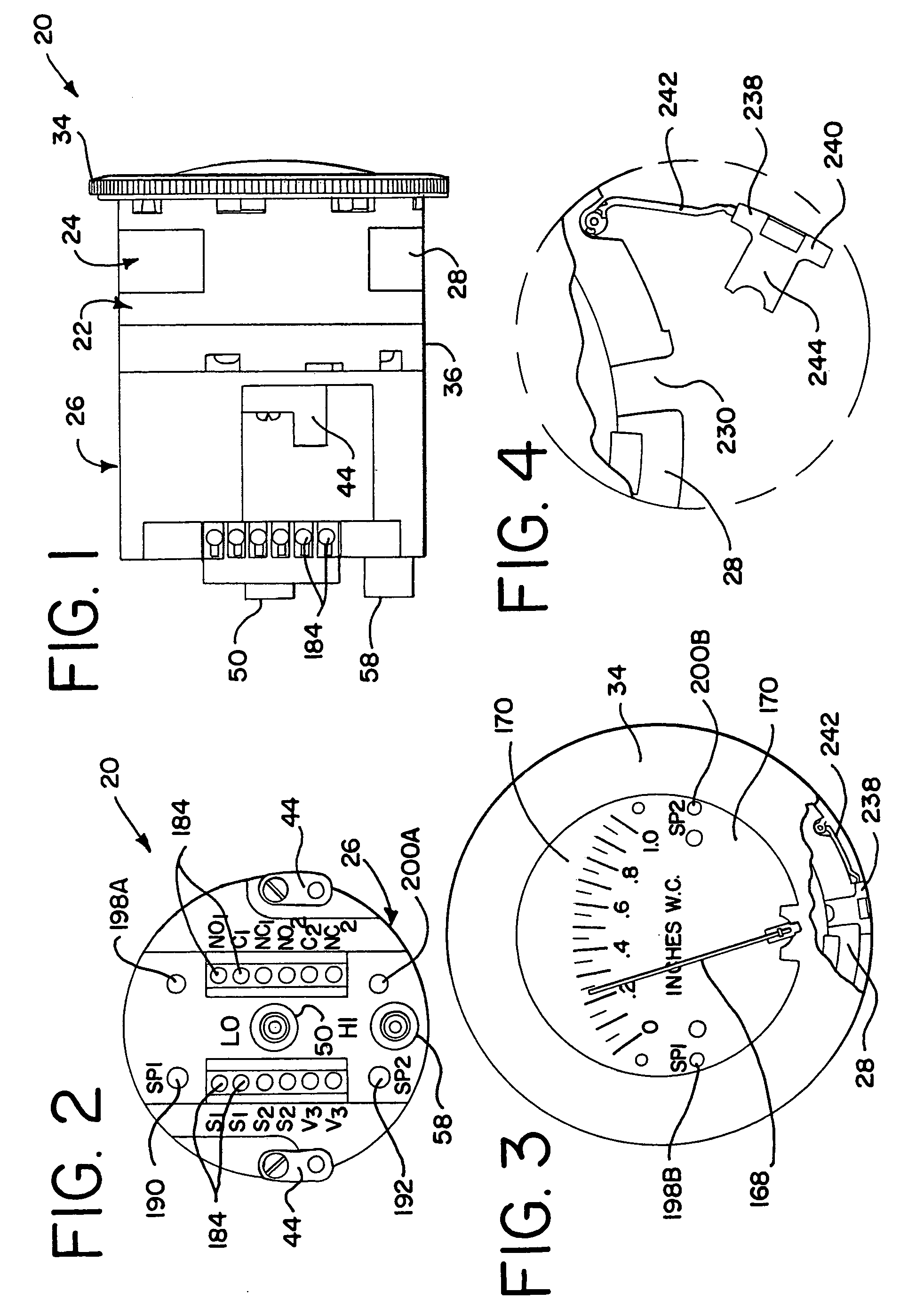
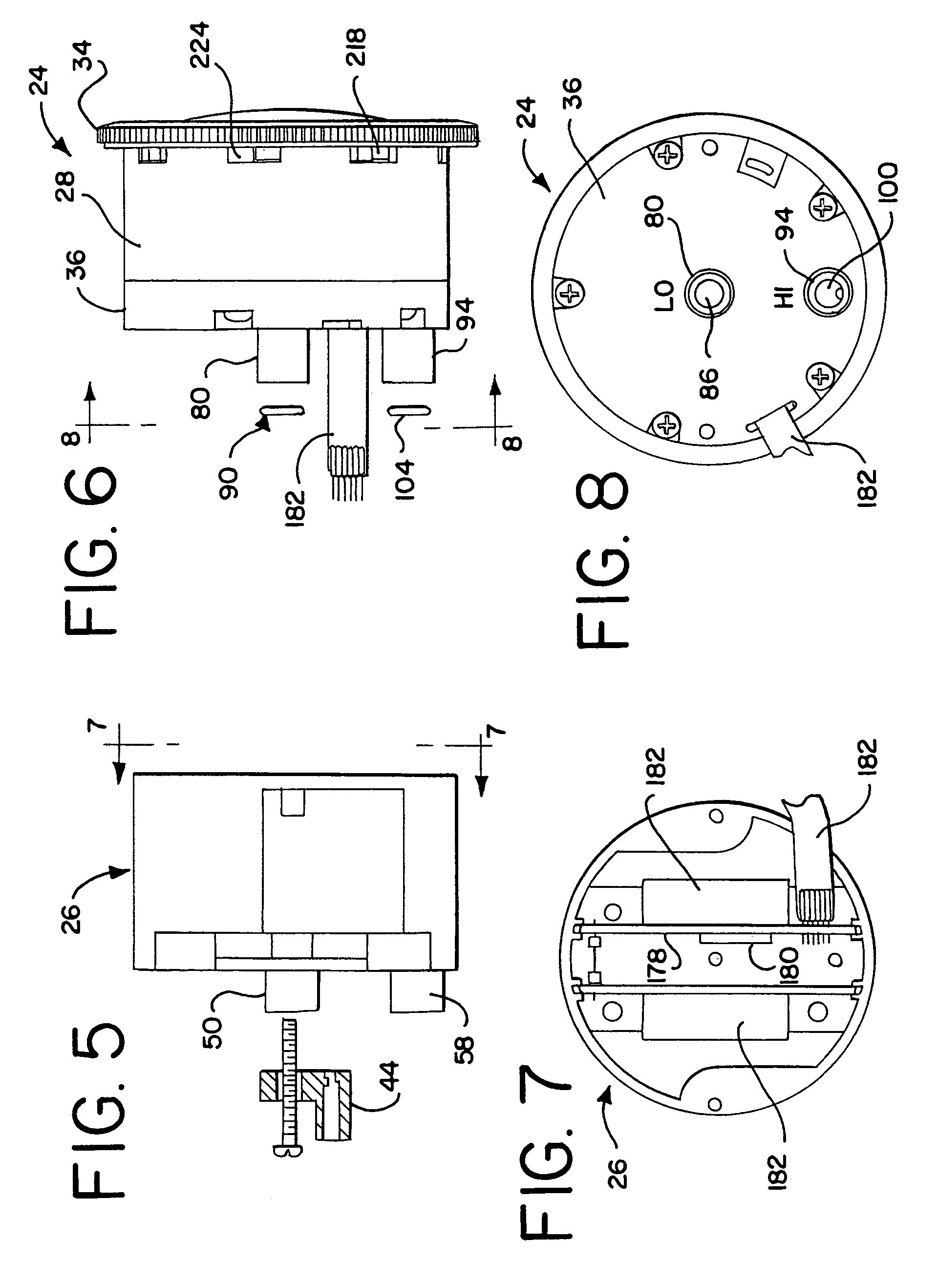
[0024]The pressure gage 20 includes a housing 22. The housing 22 includes a gage head assembly 24 that is attached to a gage body housing 26. The head assembly 24 includes a gage head housing 28 having a first end 30 and a second end 32. A cover 34 having a clear lens is attached to the first end 30 of the head housing 28. The head assembly 24 also includes a back plate 36 attached to the second end 32 of the head housing 28. The body housing 26 is attached to the back plate 36.

[0025]The body housing 26 as best shown in FIGS. 1 and 2, includes a pair of connector members 44 for removably mounting the pressure gage 20 to a panel or other stationary structure. Each connector member 44 is pivotally attached at one end to the body housing 26 by a fastener. The second end of each connector member 44 includes a bore adapted to receive a fastener for connecting the gage 20 to the stationary structure. The connector members 44 can be pivoted inwardly within the outer circumference of the bo...


PUM


Abstract

A pressure gage adapted to provide a mechanical indication of a sensed pressure and to provide an electrical signal indicative of the sensed pressure. The pressure gage includes a housing having a first fluid pressure chamber, a second fluid pressure chamber, and flexible diaphragm separating the first fluid pressure chamber from the second fluid pressure chamber. A magnet is coupled to the diaphragm such that movement of the diaphragm causes a related movement of the magnet. A helix is located adjacent to the magnet and a pointer is attached to the helix for conjoint rotation with a helix about a rotational axis. A Hall effect sensor is also located adjacent the magnet. Movement of the magnet in response to movement of the diaphragm rotates the helix and the pointer to provide a mechanical indication of the pressure sensed by the diaphragm, and the movement of the magnet causes the Hall effect sensor to generate an electrical signal indicative of the pressure sensed by the diaphragm.

Description

RELATED APPLICATIONS[0001]This application claims the benefit of U.S. Provisional Application No. 60 / 474,138, filed May 29, 2003.BACKGROUND OF THE INVENTION[0002]The present invention is directed to a pressure gage for measuring, indicating and controlling positive, negative or differential fluid pressures, and in particular to a pressure gage including a magnet coupled to a diaphragm, wherein movement of the magnet in response to pressure changes sensed by the diaphragm provides mechanical movement of a pointer to indicate the sensed pressure or pressure differential, and movement of the magnet creates a change in a magnetic field sensed by a Hall effect sensor wherein the output signal from the Hall effect sensor is connected to one or more switching relays for controlling associated devices in response to sensed pressure changes.[0003]Pressure gages such as that disclosed in U.S. Pat. No. 4,347,744 of Dwyer Instruments, Inc., the assignee of the invention described herein, have b...

Claims


Application Information

Patent Timeline
03 Jan 2006
Publication
US6981421B2
IPC
G01L9/10; G01L9/00; G01L7/08; G01L9/14
CPC
G01L9/0041; G01L7/084; G01L9/14; G01L7/08; G01L13/02; G01L13/025; H01H35/34
Inventors
PALMER, BRIAN L.; HEUER, DANIEL A.