Portable electronic system having multiple display modes for reorienting the display of data on a display screen

a technology of electronic display device and display screen, which is applied in the direction of electric digital data processing, instruments, computing, etc., can solve the problems of insufficient space in the electronic system to support multiple communication ports, high cost, etc., and achieve the effect of convenient viewing and reading of the electronic display devi

Inactive Publication Date: 2006-01-03
QUALCOMM INC
View PDF9 Cites 66 Cited by
  • Summary
  • Abstract
  • Description
  • Claims
  • Application Information

AI Technical Summary

Benefits of technology

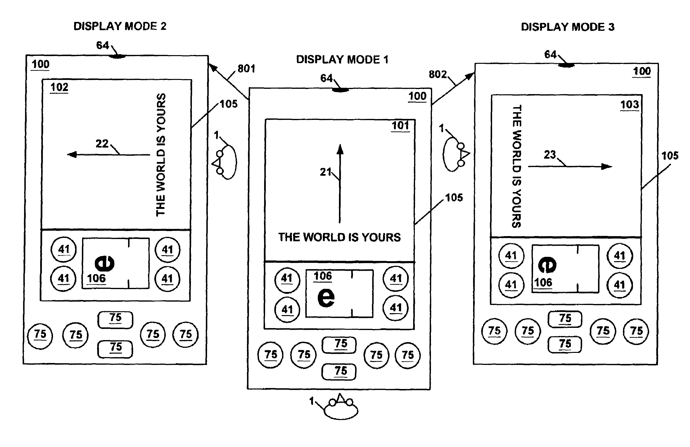
[0014]In one embodiment, the electronic system includes one or more display mode controls for enabling the user to select a particular display mode. In a second embodiment, the electronic system includes a display re-orientation selector for enabling the user to select a particular display mode. The display re-orientation selector is implemented as a graphical button displayed on the electronic display device. Alternatively, the display

Problems solved by technology

This solution is expensive.
Moreover, the electronic system may n

Method used


Image

  • Portable electronic system having multiple display modes for reorienting the display of data on a display screen
  • Portable electronic system having multiple display modes for reorienting the display of data on a display screen
  • Portable electronic system having multiple display modes for reorienting the display of data on a display screen

Examples


Embodiment Construction

[0033]Reference will now be made in detail to the preferred embodiments of the present invention, examples of which are illustrated in the accompanying drawings. While the invention will be described in conjunction with the preferred embodiments, it will be understood that they are not intended to limit the invention to these embodiments. On the contrary, the invention is intended to cover alternatives, modifications and equivalents, which may be included within the spirit and scope of the invention as defined by the appended claims. Furthermore, in the following detailed description of the present invention, numerous specific details are set forth in order to provide a thorough understanding of the present invention. However, it will be recognized by one of ordinary skill in the art that the present invention may be practiced without these specific details. In other instances, well known methods, procedures, components, and circuits have not been described in detail as not to unnec...


PUM


Abstract

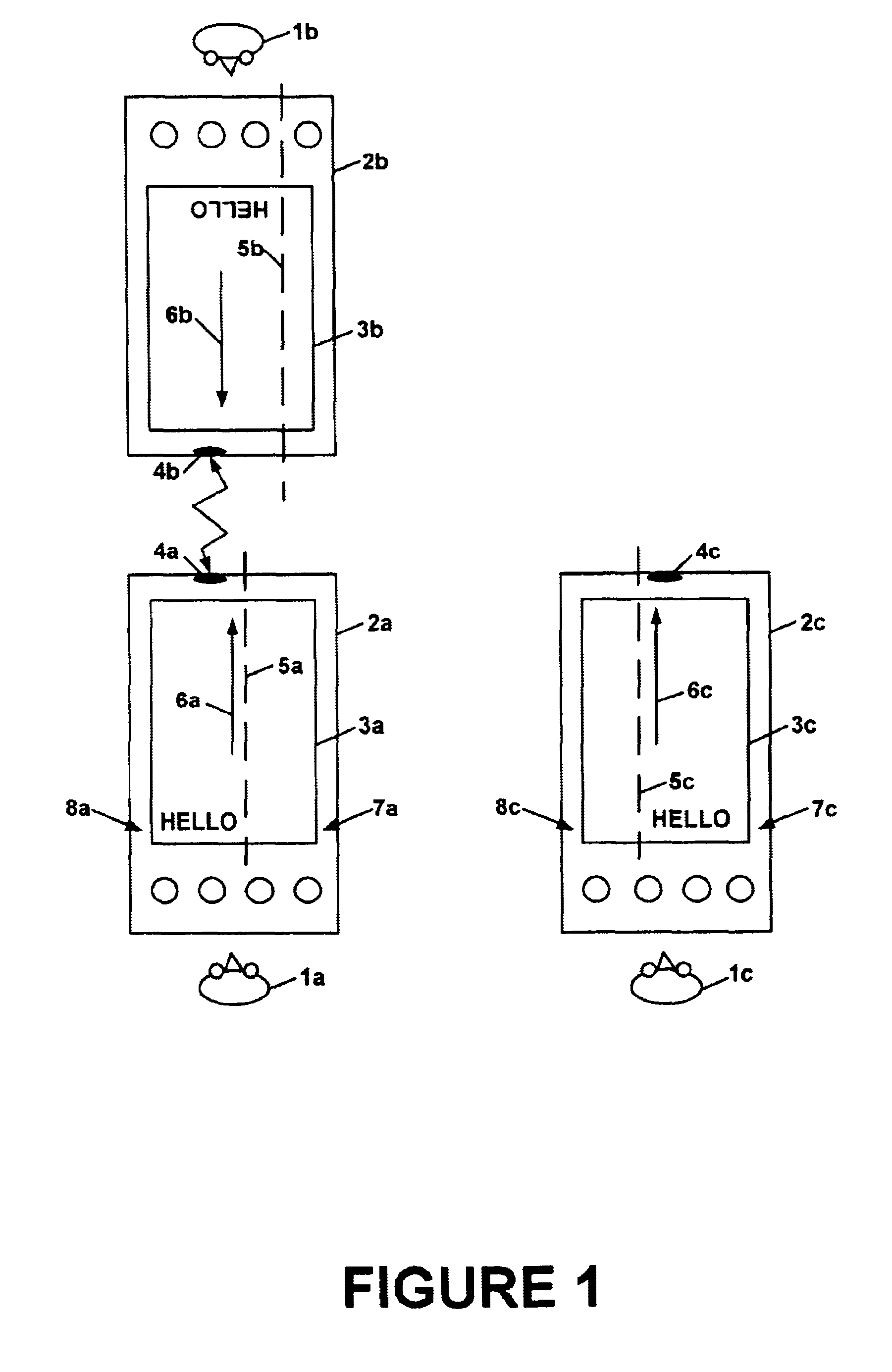
An electronic system includes an electronic display device and a communication port. Each display mode corresponds to a particular position of the communication port relative to a line of sight of a user. In one embodiment, the communication port is an infrared communication port. Each display mode corresponds to a particular display orientation. The electronic display device displays visual data in the particular display orientation corresponding to the display mode of the electronic system. In one embodiment, the electronic system is a palmtop computer system such as a personal digital assistant. A user can selectively operate the electronic system in any one of the multiple display modes for communication with a second electronic system via the communication port. The user positions the electronic system such that the communication port is located in a position facilitating communication with the second electronic system via the communication port. The user selects a particular display mode such that to align the user's line of sight with the display orientation of the electronic display device. In one embodiment, the electronic system includes one or more display mode controls for enabling the user to select a particular display mode. In a second embodiment, the electronic system includes a display re-orientation selector for enabling the user to select a particular display mode. The display re-orientation selector is implemented as a graphical button displayed on the electronic display device.

Description

BACKGROUND OF THE INVENTION[0001]1. Field of the Invention[0002]The present invention generally relates to the field of electronic systems having an electronic display device. More particularly, the present invention relates to the field of electronic systems having multiple display modes for displaying visual data in multiple display orientations on the electronic display device.[0003]2. Related Art[0004]Computers and other electronic systems or devices (e.g., personal digital assistants) have become integral tools used in a wide variety of different applications, such as in finance and commercial transactions, computer-aided design and manufacturing, health care, telecommunication, education, etc. Computers along with other electronic devices are finding new applications as a result of advances in hardware technology and rapid development in software technology. Furthermore, the functionality of a computer system or other type of electronic system or device is dramatically enhance...

Claims


Application Information

Patent Timeline
IPC IPC(8): G09G5/00
CPCG06F1/1626G06F1/1698G06F1/1632G06F2200/1614
Inventor NICOLAS, REGISTESSIER, RONALD
Owner QUALCOMM INC
Why Eureka
Try Eureka