Particulate filter regenerating device

a technology of regenerating device and particulate filter, which is applied in the direction of electrical control, exhaust treatment electric control, separation process, etc., can solve the problems of excessive heating of particulate filter, uneven distribution of particulate matter within particulate filter, and the inability to completely combust particulate matter for a long tim

Inactive Publication Date: 2006-01-10
NISSAN MOTOR CO LTD
View PDF9 Cites 39 Cited by
  • Summary
  • Abstract
  • Description
  • Claims
  • Application Information

AI Technical Summary

Benefits of technology

[0013]It is good to detect the quantity of particulate accumulated in the particulate filter (hereinafter called “accumulated particulate quantity”) and determine that it is time to regenerate the particulate filter when the detected accumulated particulate quantity reaches a prescribed quantity or when the exhaust gas temperature is equal to or greater than a prescribed temperature.
[0014]In this way, the particulate matter can be combusted completely within a short period of time after regeneration starts because regeneration is started while the quantity of accumulated particulate is still comparatively small. As a result, the frequency with which regeneration is interrupted due to the vehicle shifting to a region of low travel speed or the like while regeneration is in progress can be reduced and the particulate matter can be prevented from becoming unevenly distributed.

Problems solved by technology

It has been discovered that when the regeneration timing for regenerating a particulate filter is determined by comparing the quantity of accumulated particulate matter with a prescribed value, the following problem occurs.
Since regeneration is not commenced until a certain quantity of particulate matter has accumulated in the particulate filter, a considerable amount of time is required to combust the particulate matter completely.
When the regeneration process is interrupted repeatedly, the distribution of the particulate matter within the particulate filter becomes uneven.
Then, when regeneration is started under conditions of uneven accumulation of the particulate matter, the heating of the particulate filter becomes excessive at the portions where the particulate matter is concentrated and the durability or service life of the particulate filter declines.

Method used


Image

  • Particulate filter regenerating device
  • Particulate filter regenerating device
  • Particulate filter regenerating device

Examples


Embodiment Construction

[0026]Selected embodiments of the present invention will now be explained with reference to the drawings. It will be apparent to those skilled in the art from this disclosure that the following descriptions of the embodiments of the present invention are provided for illustration only and not for the purpose of limiting the invention as defined by the appended claims and their equivalents.

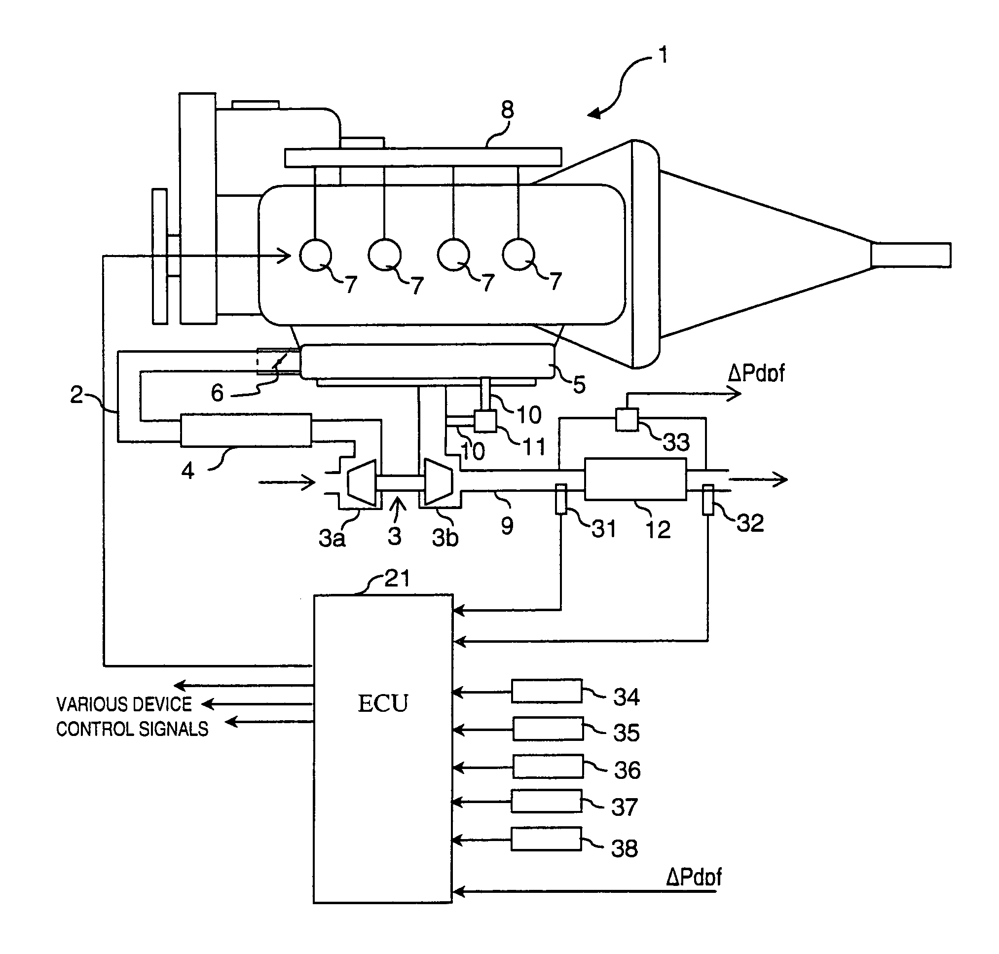
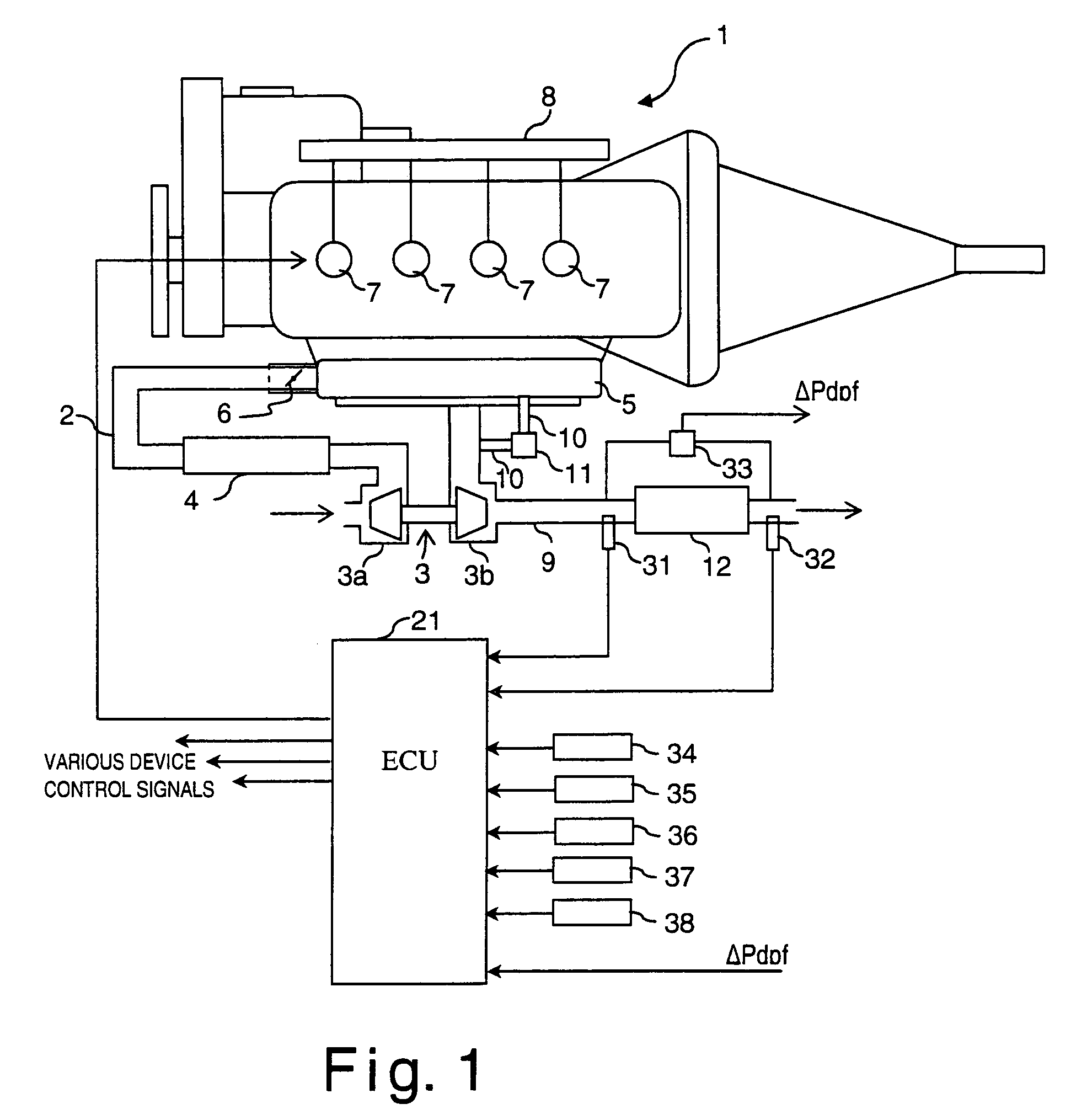
[0027]Referring initially to FIG. 1, a schematic diagram of a direct injection diesel engine 1 is illustrated in accordance with a first embodiment of the present invention. The diesel engine 1 is preferable used in an automobile. The diesel engine 1 is well known in tho art. Since diesel engines are well known in the art, the precise structure of the diesel engine 1 will not be discussed or illustrated in detail herein.

[0028]An air cleaner (not shown) is installed at the inlet part of the air intake passage 2 to remove dust and particles from intake air to the diesel engine 1. A variable nozzle tu...


PUM

PropertyMeasurementUnit
exhaust gas temperatureaaaaaaaaaa
temperature tTexhaaaaaaaaaa
exhaust gas temperatureaaaaaaaaaa

Abstract

A particulate filter regenerating device is configured to prevent the uneven distribution of particulate matter that results from interruption of the regeneration process and protect the particulate filter. The frequency with which regeneration is executed is increased by determining that it is time to regenerate the particulate filter at a time t1 when the exhaust gas temperature Texhin has reached or exceeded a prescribed temperature Texh1. Additionally, particulate filter regenerating device determines that it is time to regenerate the particulate filter when the quantity of accumulated particulate matter reaches or exceeds a prescribed value PM1. The particulate filter is regenerated by raising the temperature of the exhaust gas and combusting the accumulated particulate matter.

Description

BACKGROUND OF THE INVENTION[0001]1. Field of the Invention[0002]The present invention generally relates to a particulate filter regenerating device for a particulate filter used to after-treat the exhaust gas of engines, especially diesel engines. The present invention also generally relates to an engine exhaust gas cleaning device that utilizes such a particulate filter regenerating device.[0003]2. Background Information[0004]Diesel particulate filters are particulate matter collecting devices comprising a honeycomb monolith made of ceramic or the like. Diesel particulate filters are generally used to remove particulate substances (hereinafter called “particulates”) from the exhaust gas discharged by diesel engines. During operation, particulates gradually accumulate in the diesel particulate filter. Eventually, the quantity of accumulated particulate matter exceeds an allowed quantity and clogging occurs. Once the particulate filter is clogged, this causes the exhaust pressure to ...

Claims


Application Information

Patent Timeline
Patent Type & Authority Patents(United States)
IPC IPC(8): F01N3/00B01D46/00B01D46/24F01N3/02B01D46/46F01N3/023F01N9/00F02B3/06F02B37/00F02D21/08F02D41/02
CPCB01D46/0063B01D46/46F01N3/023F01N3/0233F01N9/002F02D41/0245F02D41/029F02B3/06Y02T10/47F02D41/0055F02D41/1446F02D2200/0812Y02T10/26F02B37/00Y02T10/12Y02T10/40B01D46/84
Inventor KONDO, TERUNORIKAWASHIMA, JUN-ICHITSUTSUMOTO, NAOYAOHTAKE, MAKOTOINOUE, TAKAOKOGA, TOSHIMASA
Owner NISSAN MOTOR CO LTD
Why Eureka
Try Eureka